Application & Construction
Systematic approach for assessing the anchorage capacity
Calculation and design of AAC parapet anchorage
Loading...

Autoclaved Aerated Concrete (AAC) parapet panels, represent a modern and efficient solution for multi-story residential or industrial constructions. These large-format, reinforced wall elements are specifically designed to meet the demands of contemporary building practices, offering both structural reliability and construction efficiency. Their high dimensional accuracy and optimized format enable AAC parapet panels to be installed rapidly and cost-effectively. This not only reduces on-site labour and scaffolding time but also minimizes storage and logistics costs. With installation rates of up to 100 linear meters per day, these elements significantly accelerate construction workflows [1].
AAC parapet panels provide a sustainable alternative to traditional reinforced concrete solutions, particularly in flat roof applications and extended parapet zones. Their thermal bridge optimization offers a clear advantage over conventional materials like reinforced concrete, while their fire resistance rating of EI 90 ensures safety in compliance with fire protection standards [1].
To construct the parapet, large‑format reinforced AAC elements are placed on the roof in a mortar bed. At the ends of the parapet elements, recesses are provided to accommodate the connection reinforcement extending from the slab, which is subsequently embedded with structural bonding by filling the recesses with concrete grout.
A critical aspect of AAC façade practice is the anchorage under dynamic actions. Proper anchorage is essential to ensure the structural stability of the system, particularly under wind loading. The elements are designed to withstand typical wind actions across various wind load zones, providing sufficient load‑bearing capacity under both pressure and suction forces. This study focuses on the structural analysis and design of the anchorage of AAC parapet elements in building construction.
Wind load and interface actions
The wind zones in Germany are divided into four zones, as shown in Fig. 1. The map of Germany and the fundamental values of the basic wind velocity vb,0 shall be determined according to the wind zone specified in Table 1.
In this work, the wind load from Zone 2 has been applied to cover the requirements of the other zones. Additionally, we propose using a whipping effect factor for all projects up to a height of 30 meters to achieve a standardized structural design applicable to all zones.
As can be seen from Fig. 1, wind zones 1 and 2 cover approximately 80 % of the country. The remaining area consists mainly of zone 3 (around 15 %) and zone 4 (about 5 %), which are primarily located in the north and along the coasts.
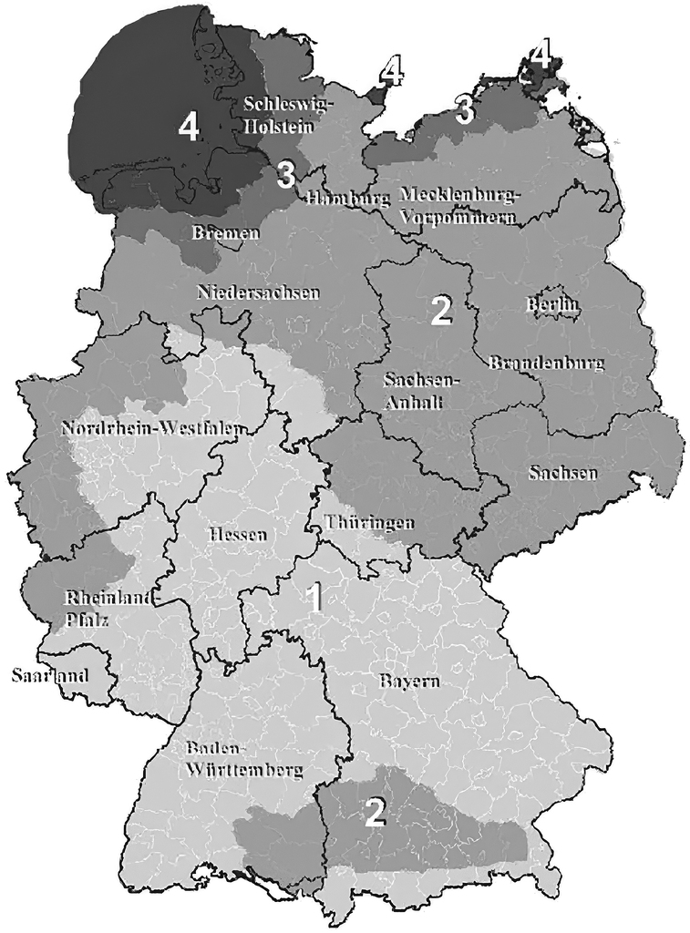
Table 1: Wind velocity and velocity pressure in different zones [2]
Zone | Wind velocity (vb,0) in m/s | Velocity pressure (qb,0) in kN/m² |
1 | 22.5 | 0.32 |
2 | 25 | 0.39 |
3 | 27.5 | 0.47 |
4 | 30 | 0.56 |
Wind whipping effect and its structural implications
The wind whipping effect refers to the dynamic response of structures to sudden changes in wind speed or direction. This phenomenon can lead to resonant vibrations, particularly in tall and slender buildings or bridges, where oscillations caused by wind forces become significant. Fig. 2 illustrates the effect of wind whipping on the parapet of a building.
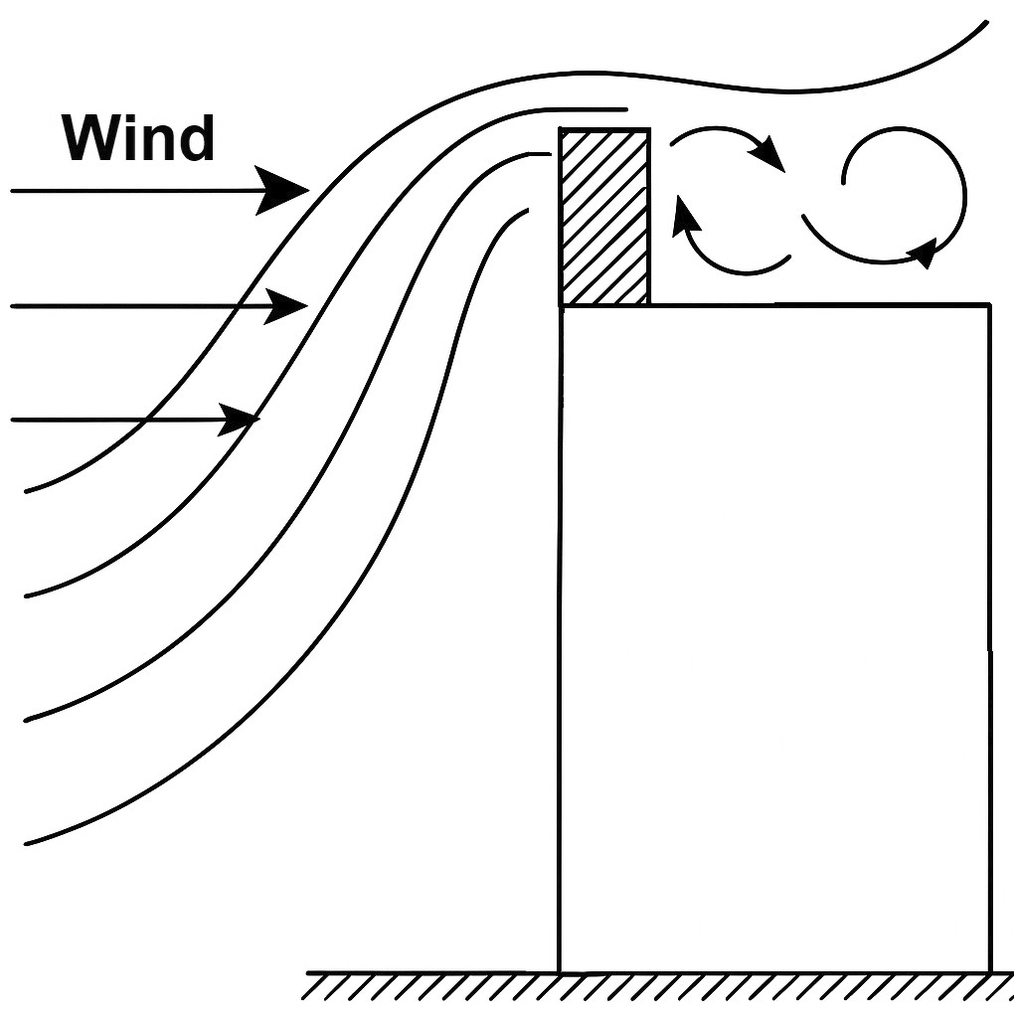
In meteorological and physical contexts, the whipping effect describes how gusts or strong winds can cause abrupt and sometimes violent movements. For example, when wind flows over a flat terrain and encounters an obstacle such as a building or hill, it may be deflected or accelerated, resulting in a sudden spike in wind intensity. This can create a wave-like motion or fluctuating wind strength. Similarly, fast-moving vehicles can experience irregular airflow, leading to a whipping sensation.
To account for these dynamic effects in structural design, a correction factor is applied based on the height and shape of the structure. Depending on the wind zone and building height, safety factors typically range between 1.0 and 2.0. For initial design estimates, a simplified approach involves using a multiplier of 1.5 to 2.0, which adjusts the calculated wind load to reflect the additional forces induced by oscillations. This consideration is crucial for ensuring structural safety and serviceability, especially in regions with high wind activity or for structures exposed to complex aerodynamic conditions.
Friction effect in the mortar bedding of AAC parapets
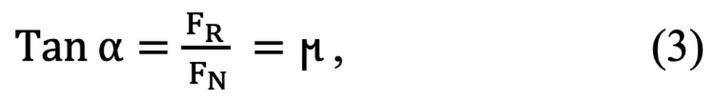
When a parapet element is placed on a roof using a mortar bed, a frictional force develops at the interface between the parapet element and the mortar. This frictional force, FR, acts parallel to the contact surface and counteracts any relative displacement of the element. The normal force, FN, acting perpendicular to the contact surface, is generated by the self‑weight of the parapet element. The resulting frictional resistance can be calculated as:

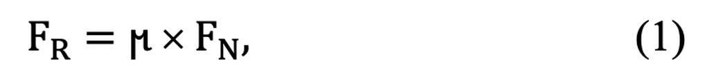
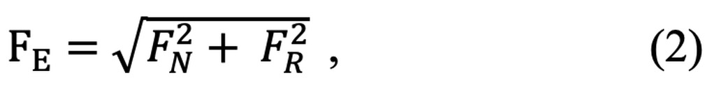
where μ is the coefficient of friction, representing the roughness and adhesion characteristics of the contact surfaces. The combined effect of the normal force and the frictional force can be expressed through the resultant force Fe, oriented at the friction angle α. This angle is defined by:


Frictional resistance plays an essential role in stabilizing wall elements by restricting movement and ensuring that the components remain securely anchored to the roof structure. Typical friction coefficients for AAC are as follows:
· AAC on AAC: μ ≈ 0.5 – 0.6
· AAC on mortar: μ ≈ 0.4 – 0.6
· AAC on concrete: μ ≈ 0.5 – 0.7
For the purposes of this study, a friction coefficient of μ = 0.6 is adopted.
Calculation and results
Assumptions
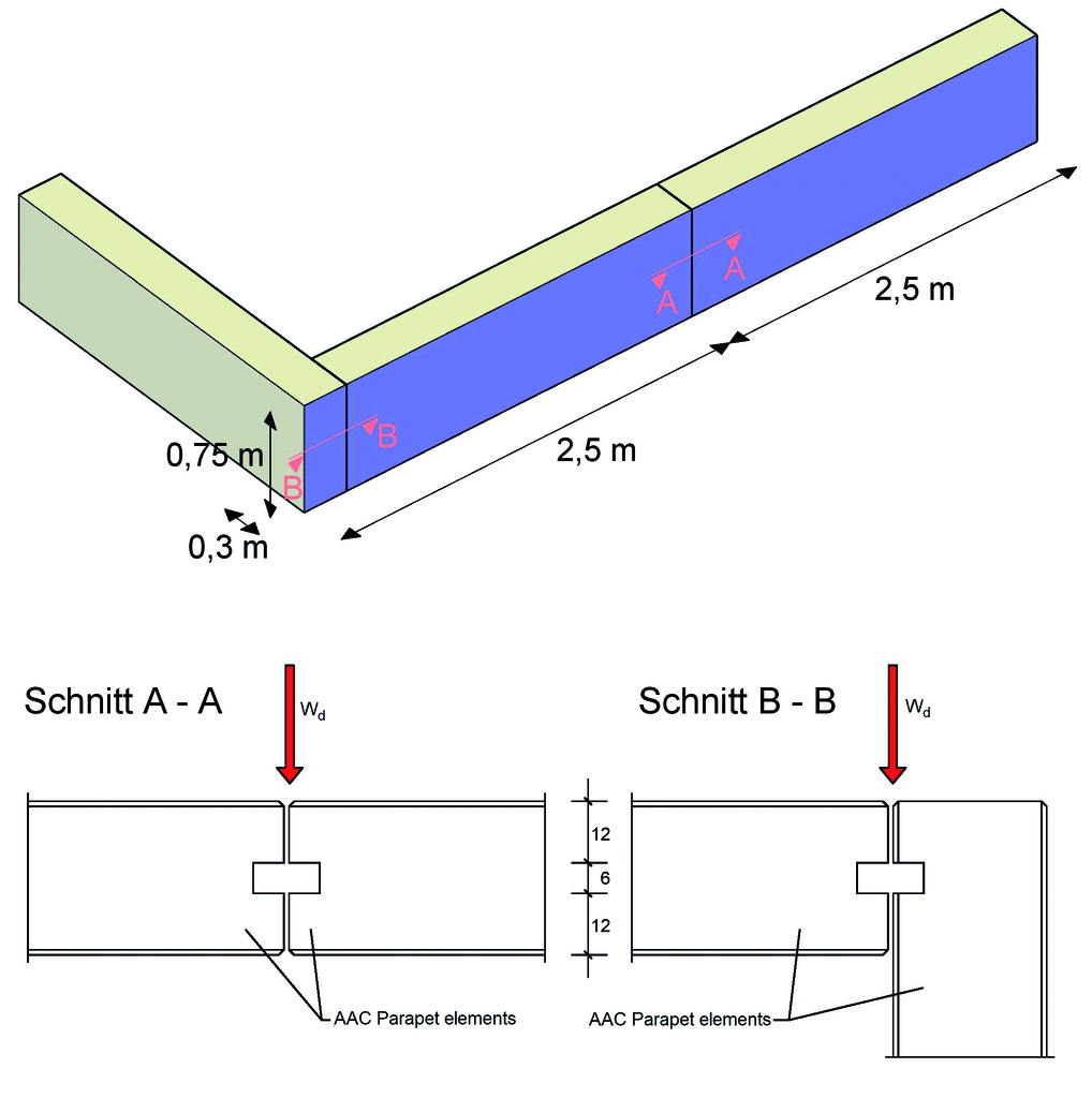
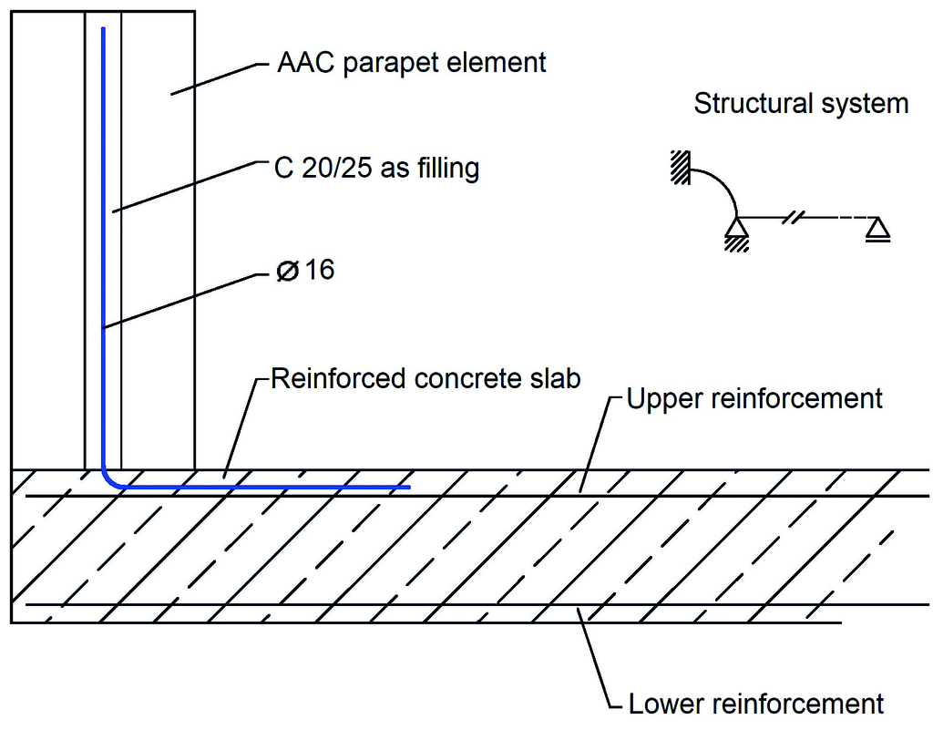
The AAC panels have dimensions of meters in length (L1, L2), 0.75 meters in height (h), and 0.3 meters in thickness (d) and compressive strength class of 4.5 N/mm² and the design weight density of γ = 6.7 kN/m³ (~ 670 kg/m3). A schematic view of the panels and their cross-section is shown in Fig. 3, while the structural system considered for the object is illustrated in Fig. 4.
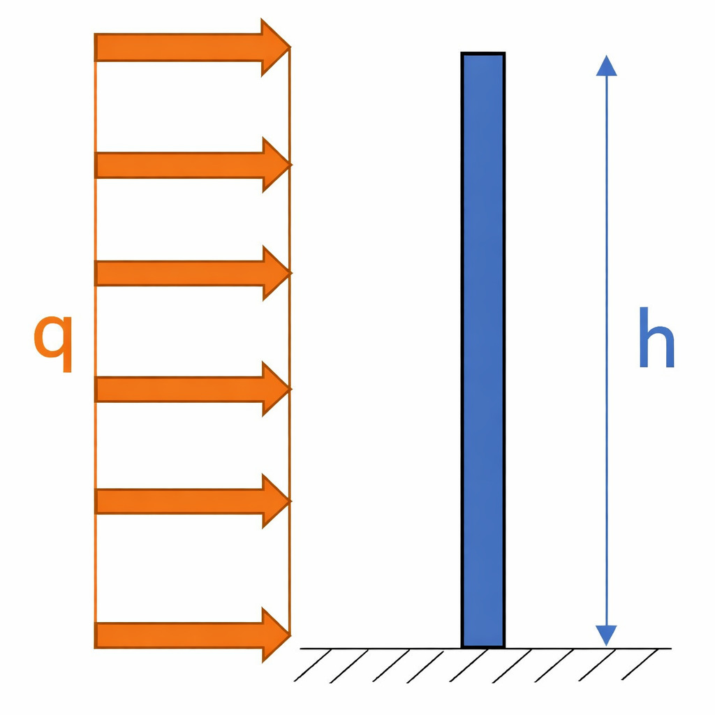
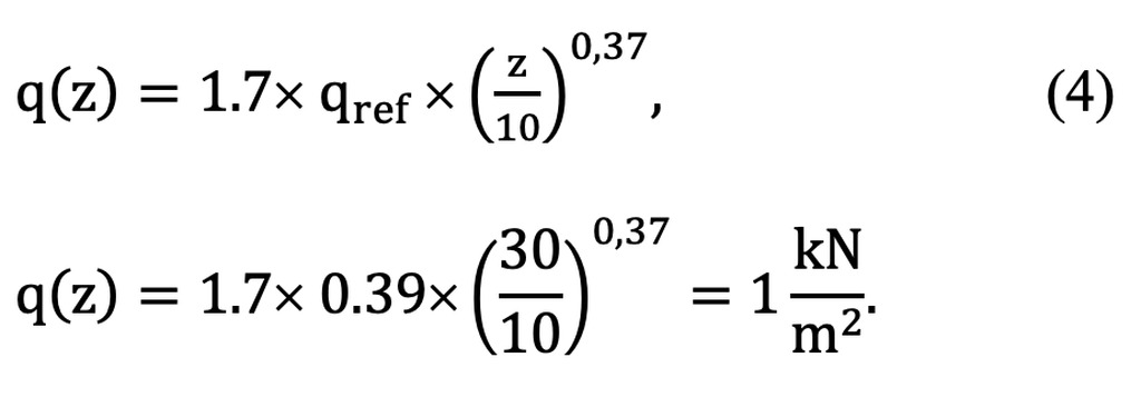
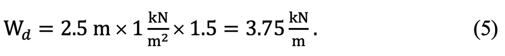
In total, wind load zones 1 and 2 cover majority of the entire Germany. For the purposes of this study, the wind action is evaluated based on the assumptions for wind load zone 2 and a reference height of H = 30 m. The wind pressure at height z is calculated using Equation 4:

A factor of 1.5 is applied to the wind load to account for the whipping effect, and the anchorage reinforcement:

Resistor components
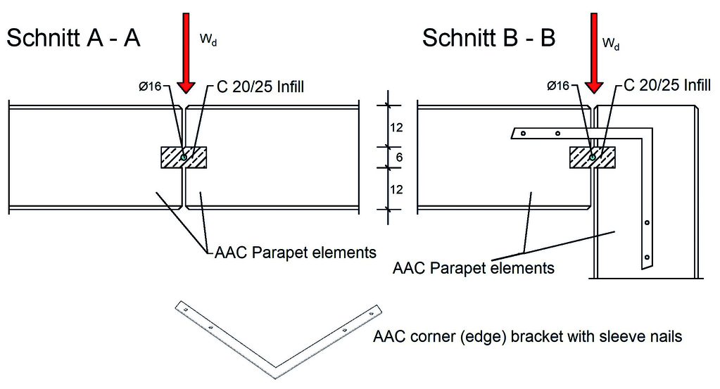
The components providing the contact mechanics required to resist wind loads include the AAC parapet element through its self‑weight, the C20/25 concrete infill in the groove, and a rebar located between the parapet elements and within the groove, which is anchored to the reinforced concrete slab. Fig. 5 shows the schematic system and the dimensions of the wind‑resisting components.
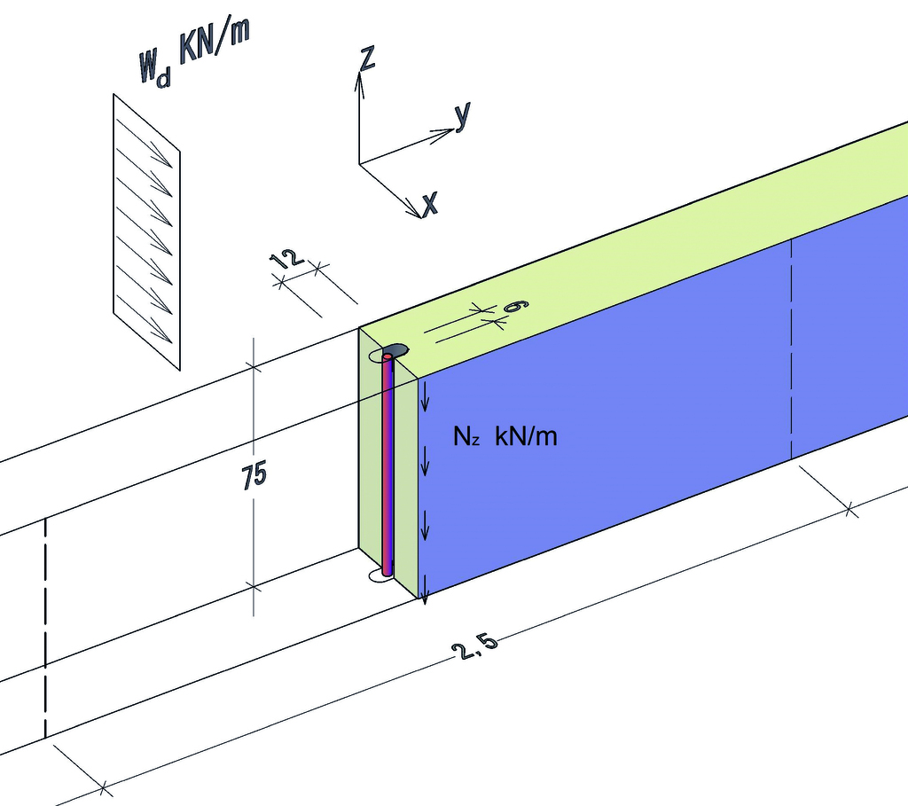
Based on what is shown in Fig. 5, the axial force labeled Nz (kN/m) acts in the vertical z‑direction along the AAC element.


where γ (kN/m³) is the design weight density of the AAC panel, and l (m) and d (m) are the length and the thickness of the panel, respectively. The sum of all the friction forces is Rz (kN/m) that will be calculated from the Equation 7. W* in Equation 8 represents the wind load reduced for friction effects and is used in the subsequent calculations.


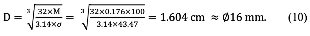
The required dimension of the rebar is calculated as below:

In this study, the design assumption was based on Wind Zone 2. However, the same calculation approach may also be applied and adjusted for Wind Zones 3 and 4, provided that the structural verification is carried out and the final decision is made by the responsible designer.
Constructive recommendations
First, the parapet elements are laid on the finished reinforced concrete slab using a bed of mortar. Afterward, the Ø16 rebars extending from the roof slab are positioned into the grooves of the parapet elements. Once all elements are in place and properly aligned, the grooves are filled with C20/25 concrete to complete and secure the system. Fig. 6 and Fig. 7 show the execution details of the parapets, where the Ø16 rebar is placed between the AAC elements and the groove is filled with C20/25 concrete.
References
[1] Xella Deutschland GmbH: Die einfache Lösung für den oberen Gebäudeabschluss: Ytong Attikaelemente, www.xella.de/de_DE/ytong/produkte/attikaelement, Stand 06/2025.
[2] DIN EN 1991-1-4/NA:2010-12: National Annex – Nationally Determined Parameters – Eurocode 1: Actions on structures – Part 1-4: 99 General actions – Wind actions; Beuth-Verlag: Berlin, 2010.