Application & Construction
Experimental investigation into earthquake and strong wind load cases
Coupled autoclaved aerated concrete confined walls subjected to lateral loads
Loading...
Jorge Varela-Rivera is a Professor at the Autonomous University of Yucatan, Merida, Yucatan, Mexico. He received his BS in civil engineering from the same university in 1993; MS in structural engineering from the National Autonomous University of Mexico, Mexico City, Mexico, in 1997; and Ph.D. in structural engineering from the University of Texas at Austin, Austin, Texas, in 2003. His research interests include the behavior of masonry structures and reinforced concrete structures with corrosion. vrivera@correo.uady.mx

Juan Cacep-Rodriguez received his BS in civil engineering from the Juarez Autonomous University of Tabasco, Cunduacan, Tabasco, Mexico, in 2016; MS and Ph.D. in structural engineering from the Autonomous University of Yucatan, Merida, Yucatan, Mexico, in 2019 and 2024, respectively. His research interests include the behavior of masonry structures. juan_cacep@hotmail.com

Luis Fernandez-Baqueiro is a Professor at the Autonomous University of Yucatan, Merida, Yucatan, Mexico. He received his BS in civil engineering from the same university in 1995; MS and Ph.D. in structural engineering from the National Autonomous University of Mexico, Mexico City, Mexico, in 1997 and 2002, respectively. His research interests include the behavior of masonry structures and finite element analysis. luis.fernandez@correo.uady.mx

Joel Moreno-Herrera is an Associate Professor at the Autonomous University of Yucatan, Merida, Yucatan, Mexico. He received his BS in civil engineering, MS and Ph.D. in structural engineering from the same university in 2008, 2010, 2014, respectively. His research interests include the behavior of masonry structures and reinforced concrete structures with corrosion. joel.moreno@correo.uady.mx
Autoclaved Aerated Concrete (AAC) structures are used in many countries around the world. These structures are being constructed in areas of strong hurricanes and severe earthquakes. One of the main lateral load systems for AAC structures under those wind and earthquake actions is coupled walls. This structural system can be constructed using AAC confined masonry walls and reinforced concrete coupling beams. In general, there are few experimental studies on the behavior of AAC confined walls subjected to lateral loads. This shows that more studies are still needed to develop rational design recommendations for structures constructed with that type of walls. For example, in Mexico, there are requirements for the design of confined masonry walls constructed with concrete blocks or clay bricks, but unfortunately, AAC units are not explicitly considered in those requirements. The goal of this paper is to present the main results of a study on the shear behavior of coupled AAC walls subjected to lateral loads as those observed during hurricanes and earthquakes. More details of the behavior of coupled AAC confined walls are presented in Varela et al. (2025).
Experimental investigation
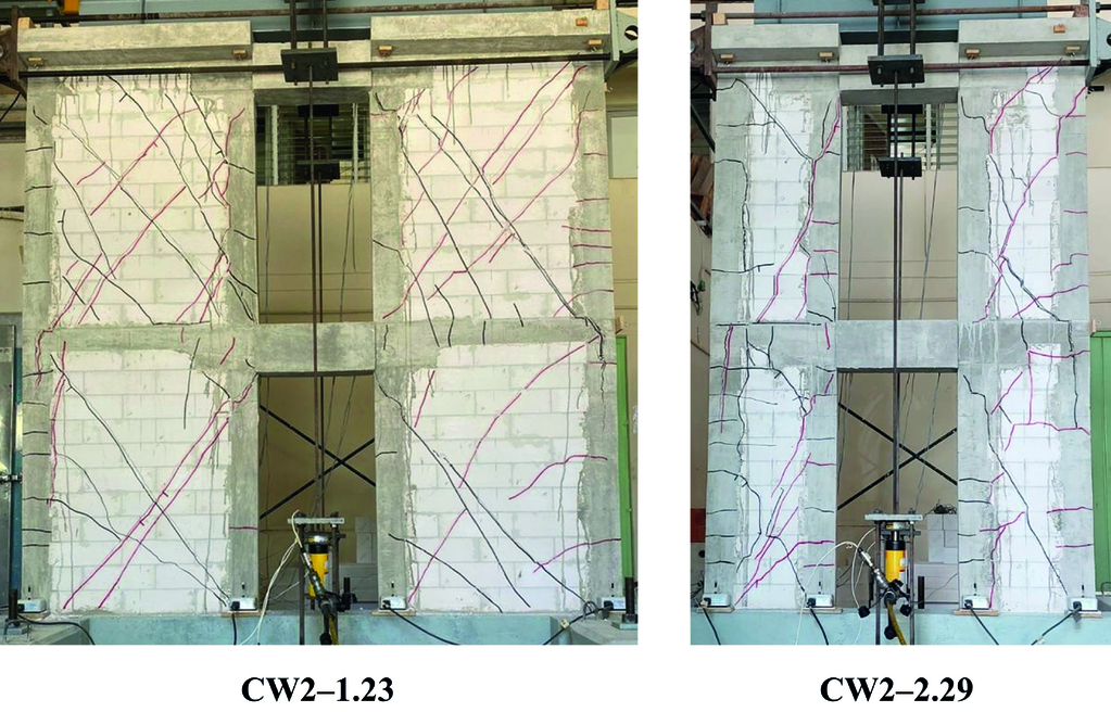
In this study 1:2 reduced scale AAC coupled walls were considered. Two one- and two two-story high coupled walls were selected (Fig. 1). In the first case, the coupled walls consisted of two individual AAC confined walls and one reinforced concrete coupling beam. In the second case, the coupled walls consisted of four individual AAC confined walls and two reinforced concrete coupling beams. The thickness of AAC confined walls was 75 mm. Coupling beam dimensions were 150 x 200 x 500 mm (width x height x length). The aspect ratios of individual AAC confined walls were equal to 1.23 and 2.29. The aspect ratio was defined as the ratio between the height of an individual wall and its corresponding length. One-story coupled AAC walls were defined based on those aspect ratios as CW1–1.23 and CW1–2.29. Similarly, two-story coupled walls were defined as CW2–1.23 and CW2–2.29 (Fig. 1).
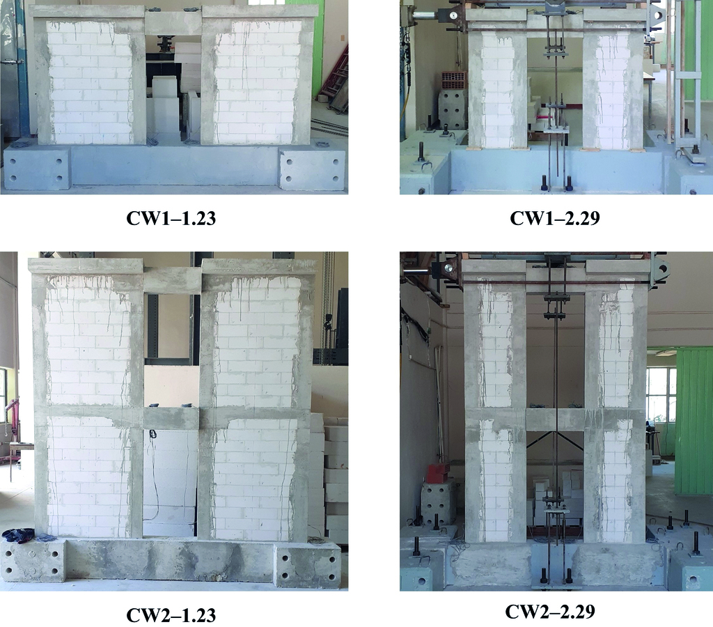
AAC class 4 solid blocks were considered for the walls. Dimensions of reduced-scale blocks were 75 x 100 x 300 mm (width x height x length). Cross section dimensions of vertical confining elements were equal to 75 x 110 mm (width x height). Cross section dimensions of intermediate horizontal confining elements of two-story coupled AAC walls were equal to 75 x 100 mm (width x height).
Coupled AAC walls were constructed by an experienced worker. AAC confined walls were constructed in half running bond. The first block course was laid using both mortar in proportions by volume 1:3 (Portland cement: sand) and thin bed mortar. The first one was used on the leveling bed joint and the second on the head joints. Subsequent block courses were laid using only thin bed mortar. A 13 mm tooth was used at end blocks of alternating courses of AAC confined walls. The layout of coupled AAC walls is presented in Fig. 1.
The compressive strength of AAC was equal to 4.69 MPa with a coefficient of variation (CV) of 0.02. The compressive strength of leveling bed mortar was equal to 17.92 MPa with a CV of 0.02. The compressive strength of thin bed mortar was equal to 10.52 MPa with a CV of 0.02. The compressive strength of concrete of vertical confining elements was equal to 27.49 MPa with a CV of 0.05. The compressive strength of concrete of coupling beams was equal to 32.53 MPa with a CV of 0.04.
Coupled AAC walls were tested under constant axial load and reverse cyclic lateral loads until failure. Axial loads were applied at the top of the coupled AAC walls. A gravity axial compressive stress of 0.29 MPa was considered for the AAC confined walls. Axial load was applied using a hydraulic actuator and was measured using two donut type load cells. Lateral loads were applied at the top of the coupled AAC walls. These loads were applied using a two-way hydraulic actuator. Lateral load was measured using a pin load cell. The test setup used for the one- and two-story coupled AAC walls are presented in Fig. 2 and Fig. 3, respectively.
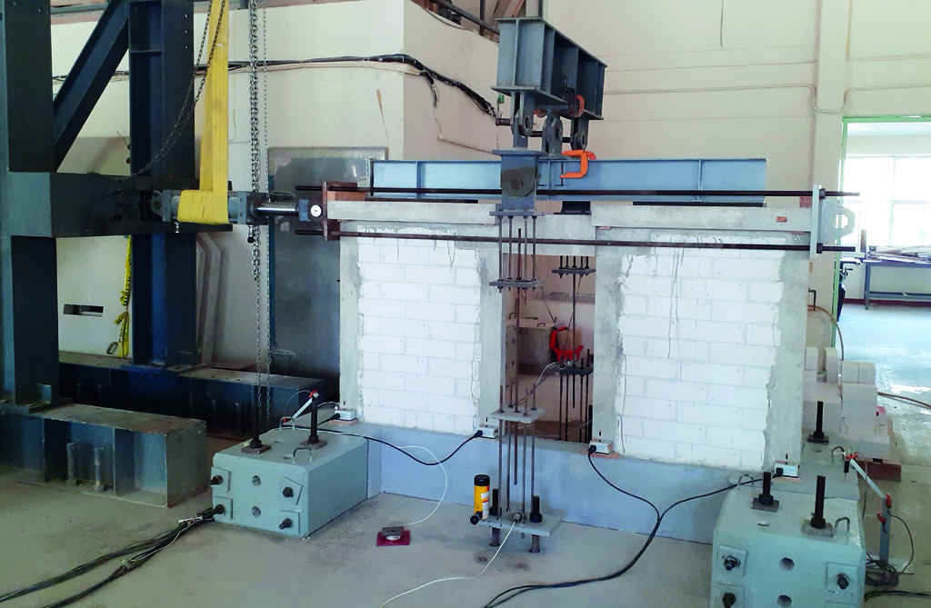
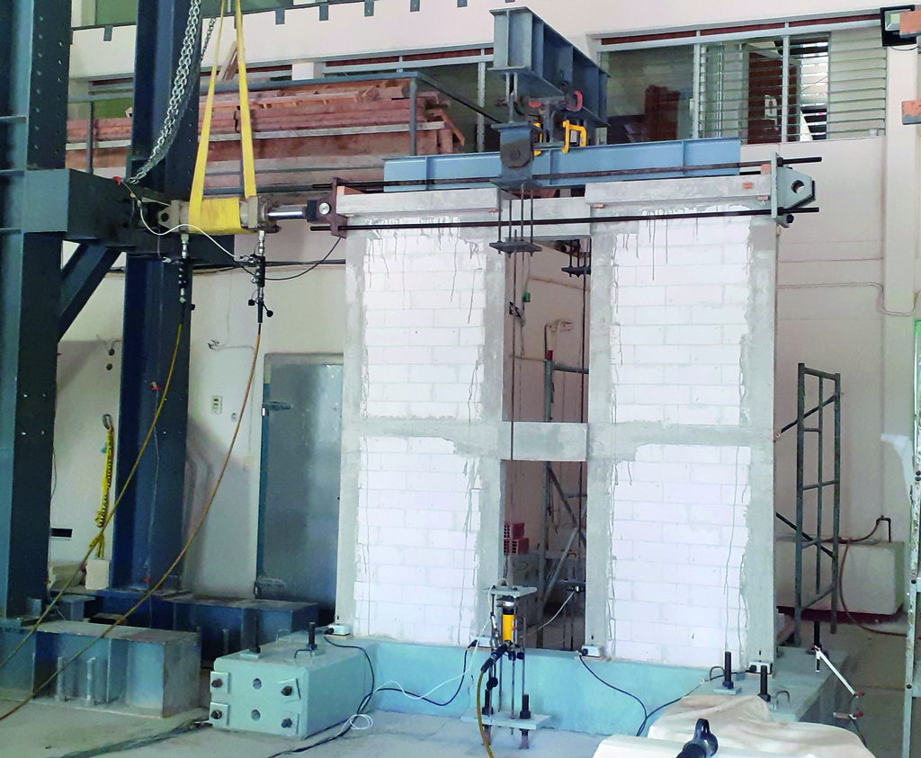
Horizontal and vertical wall displacements were measured using linear string potentiometers. Relative displacements between the coupled wall and the wall foundation, and the wall foundation and the reaction floor were measured using linear potentiometers. All wall displacements and loads were measured using a data acquisition system connected to a computer. AAC coupled walls were tested under monotonic incremental cyclic lateral loads until failure. This loading protocol was used to simulate wind and earthquake loads.
Experimental results
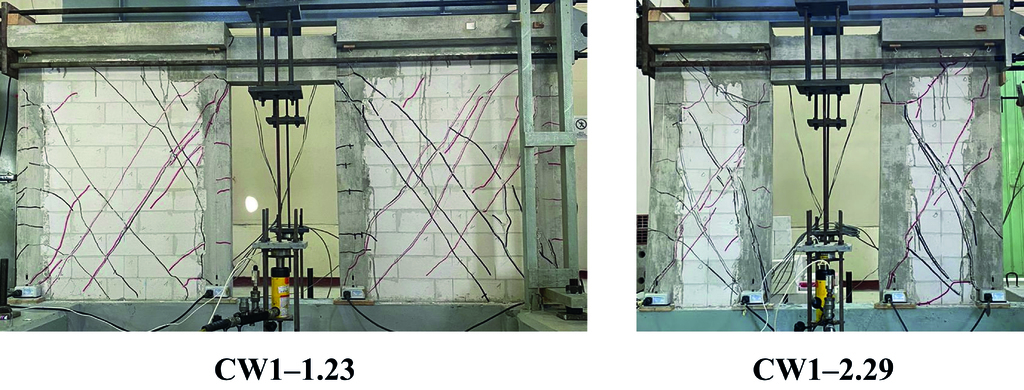
The behavior of the one-story coupled AAC walls (CW1–1.23 and CW1–2.29) was in general similar. The behavior was characterized by the formation of vertical flexural cracks at the ends of the coupling beam. After this, horizontal flexural cracks were observed on the bottom part of the vertical confining elements and at the base of AAC confined walls. As the lateral load increased, diagonal shear cracks were observed on the AAC wall panels. As the drift ratio increased, new diagonal cracks were observed on the AAC wall panels forming the traditional “X” final cracking pattern. Diagonal cracks were observed on the AAC units and not at joints. This shows that individual AAC confined walls behaved as monolithic walls. Failure of the one-story coupled walls was associated with the propagation of diagonal shear cracks into the ends of vertical confining elements of AAC confined walls. The final cracking pattern of one-story coupled AAC walls is presented in Fig. 4.
The behavior of the two-story coupled AAC walls (CW2–1.23 and CW2–2.29) was in general similar. The behavior was characterized by the formation of vertical flexural cracks at the ends of the first story coupling beam. Horizontal flexural cracks were observed on the bottom part of the first story vertical confining elements and at the base of the first story AAC confined walls. After this, diagonal shear cracks were observed on the first story AAC wall panels. Vertical flexural cracks were observed at the ends of the second story coupling beam together with propagation of horizontal flexural cracks on vertical confining elements and diagonal shear cracks on the first story AAC wall panels. As the lateral load increased, diagonal shear cracks were observed on the second story AAC wall panels. As the drift ratio increased, new diagonal cracks were observed on the first and second story AAC wall panels forming the traditional “X” final cracking pattern. Failure of the two-story coupled walls was associated with the propagation of diagonal shear cracks into the ends of vertical confining elements of AAC walls. The final cracking pattern of two-story coupled AAC walls is presented in Fig. 5.
The envelope of the lateral load – drift ratio curves of the coupled AAC walls are presented in Fig. 6. The experimental shear strength (VT) of coupled AAC walls is presented in Fig. 6 with a triangular marker. This strength is associated with the total lateral load observed at first diagonal cracking of any of the AAC confined walls. Experimental maximum shear strength (Vm) of coupled AAC walls is presented in Fig. 6 with a square marker. This strength is associated with the total maximum lateral load observed for the coupled AAC walls.

The experimental shear strength (VT) of CW1–1.23 was greater than that of the CW1–2.29 (Fig. 6). This was associated with the smaller aspect ratio (H/L) of the individual walls of CW1–1.23 compared with those of CW1–2.29. For a constant wall height, as the wall length increases, the wall aspect ratio decreases. Similarly, the experimental shear strength (VT) of CW2–1.23 was greater than that of the CW2–2.29 by the reasons describe before. The Vm/VT ratios observed for CW1–1.23 and CW1-2.29 were equal to 1.63 and 1.30, respectively. Similarly, the Vm/VT ratios observed for CW2–1.23 and CW2-2.29 were equal to 1.86 and 1.45, respectively. The Vm/VT ratios represent the shear strength of coupled walls after the first diagonal cracking of any individual AAC wall.
Final remarks
The cracking pattern of the one- and two story coupled AAC walls was similar, respectively. This cracking pattern was mainly characterized by the formation of vertical flexural cracks at the ends of coupling beams, horizontal flexural cracks along the height of vertical confining elements, and diagonal shear cracks on the AAC wall panels. The final cracking pattern of individual AAC confined walls was the traditional “X” type cracking pattern. Failure of coupled walls was associated with propagation of diagonal cracks into the ends of vertical confining elements of AAC confined walls.
The shear strength of one- and two-story coupled AAC walls increased as the wall length of individual walls increased. The Vm/VT ratios observed for CW1–1.23 and CW1-2.29 were equal to 1.63 and 1.30, respectively. Similarly, the Vm/VT ratios observed for CW2–1.23 and CW2-2.29 were equal to 1.86 and 1.45, respectively. The Vm/VT ratios represent the shear strength of coupled walls after the first cracking of any individual AAC wall.
Acknowledgements
AAC blocks and thin bed mortar were provided by Aircrete Mexico.
Reference
Varela-Rivera, J., J. Cacep-Rodríguez, L. Fernández-Baqueiro, and J. Moreno-Herrera. 2025. “Shear Strength of Coupled Autoclaved Aerated Concrete Confined Masonry Walls”. ASCE J. Struct. Eng., 151 (3). https://doi.org/10.1061/JSENDH.STENG-13764