Application & Construction
Engineering-based optimization for estimating impact loading / special applications in data centers
Fire walls made of AAC
Loading...
Ehsan Harirchian is a senior researcher and structural engineer specializing in the design of earthquake-resistant buildings. He has accumulated extensive experience and has published widely in the fields of seismic engineering and vulnerability assessment. He is recognized for his expertise in structural performance evaluation, earthquake data analysis, and the study of building behavior in seismically active regions, with a particular emphasis on sustainable construction materials. In his current role, he contributes to advancing complex engineering and research projects by supporting both analytical and design processes. He maintains rigorous technical standards throughout all phases of project development, from conceptualization to implementation.
ehsan.harirchian@uni-weimar.de

Kamran Farid is a highly experienced structural engineer specializing in AAC systems. With over 25 years of professional experience in the AAC field, he is recognized for his deep technical expertise in material behavior, structural performance, and the practical implementation of AAC solutions.
In his role, he leads engineering teams, supports complex project development, and ensures high technical quality across all design and execution phases. His extensive industry knowledge and hands-on experience make him a key contributor to innovation and reliability in AAC-based construction projects in Germany and across Europe.
Fire safety of AAC
AAC is a mineral, non-combustible building material classified as A1 according to DIN 4102-1 [1] and DIN EN 13501-1 [2]. It exhibits minimal smoke development (class s1) and does not produce flaming droplets or particles (class d0). This classification is maintained even when common coatings or wall claddings are applied. The homogeneous, porous structure of AAC results in low thermal conductivity, contributing to highly favorable fire performance. Components constructed from AAC rarely develop cracks or joints under intense heat and maintain resistance to fire gas and smoke penetration. When appropriate wall thickness, density, strength class, and structural design are ensured, AAC walls fulfill the requirements for fire walls as specified in Section 30 of the German Model Building Code (Musterbauordnung, MBO) [3] or the relevant state building codes.
Areas of application for AAC fire walls
External fire walls
External fire walls are used when buildings are erected directly on the property boundary or when the required distances to neighboring buildings cannot be maintained. They prevent fire from spreading to adjacent buildings or properties. AAC offers particularly favorable conditions for this due to its non-combustibility, high fire resistance, and temperature-limiting properties; the solid mineral construction enables reliable fire separation without the need for additional combustible protective layers.
Internal fire walls
Internal fire walls divide larger buildings into separate fire compartments, thereby limiting the spread of fire and creating the conditions necessary for effective rescue and firefighting operations. Autoclaved aerated concrete fire walls are frequently used, particularly in large industrial and warehouse buildings, which are referred to in the MBO [3] as “extensive buildings,” because they combine high fire resistance with a robust and durable construction. There is no universally applicable definition of building size; the specific requirements are determined by the respective state building regulations and by occupancy-specific requirements and regulations.
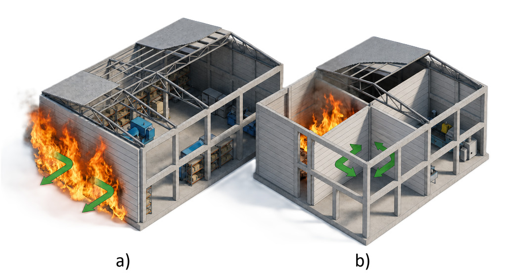
Figure 1 illustrates the application of AAC wall panels as fire walls for both internal and external fire protection. As can be seen, the fire wall acts as an effective barrier against the spread of fire, preventing fire penetration into adjacent building sections or neighboring structures. By maintaining compartmentation and limiting the transfer of heat, flames, and smoke, the wall helps contain the fire within the affected area, thereby protecting occupants, reducing property damage, and facilitating firefighting and rescue operations.
Regulatory classification
The European classification system defined by DIN EN 13501-2 [4] differentiates between load-bearing and non-load-bearing structures. Non-load-bearing fire walls receive the designation EI-M, whereas load-bearing fire walls are designated as REI-M. Table 1 provides the definitions and applications of these classifications.
Table 1: Definitions and applications of fire resistance classifications (adopted from [4])
Designation | Meaning | Applies to |
R – Résistance | Load-bearing capacity | load-bearing walls only |
E – Étanchéité | Integrity (room enclosure) | all fire walls |
I – Isolation | Insulation | all fire walls |
M – Mechanical action | Resistance to impact loading | all fire walls |
Fire resistance and temperature behavior
The fire response of construction materials is primarily determined by their thermal and mechanical properties. At elevated temperatures, steel components gradually soften and lose load-bearing capacity, while metal sheets may buckle locally or melt. Conventional concrete is susceptible to thermal cracking, deformation, and spalling, which can compromise compartmentation and facilitate the transmission of smoke and hot gases. In contrast, AAC exhibits superior fire resistance due to its porous microstructure and low thermal conductivity. Its dimensional stability under thermal loading reduces crack formation and maintains the barrier function of walls and partitions. Furthermore, the superior thermal insulation properties of AAC significantly limit temperature increases on the unexposed side of structural elements, thereby offering enhanced fire protection compared with conventional concrete materials. Table 2 presents the temperature dampening through a 150 mm thick wall and compares the thermal performance of AAC and conventional concrete under fire exposure.
Table 2: Comparison of temperature dampening in AAC and normal concrete walls (adopted from [5])
Wall; d = 150 mm | Surface temperature (side facing away from fire) after 6 Hours |
AAC, 500 kg/m³ | < 70 °C |
Normal concrete | ≥ 270 °C |
According to a test certificate issued by MPA Braunschweig [6], AAC fire wall panels achieve a fire resistance rating of up to 360 minutes, significantly exceeding typical regulatory requirements. AAC elements with a thickness of 150 mm meet fire resistance class EI 240, while wall panels with a thickness of 175 mm have been verified to provide fire resistance for up to 360 minutes (EI 360 or F 360).
Structural design
Wall construction and minimum thickness
For single-leaf construction, fire walls composed of AAC wall panels with a compressive strength/density class of AAC 4.5-550 must have a minimum thickness of 175 mm. In double-leaf construction, the minimum wall thickness is 2 × 175 mm. The German Industrial Building Directive (Industriebaurichtlinie) [7] specifies that larger fire compartments may require fire walls to be tested for impact loading after 120 minutes, rather than the standard 90 minutes. In such cases, a minimum wall thickness of 200 mm is mandated. Table 3 presents the minimum wall thickness and axis spacing requirements for AAC fire walls, including the increased thickness necessary for fire walls subjected to impact loading after 120 minutes of fire exposure.
Table 3: Required wall thickness and minimum axis spacing for fire walls subjected to impact loading (adopted from [8])
Impact loading tested after | Minimum thickness | Minimum axis spacing |
90 minutes | 175 mm | 30 mm |
120 minutes | 200 mm | 30 mm |
Panels are consistently joined along their longitudinal edges using a tongue-and-groove profile. For fire walls and high-performance partition walls, longitudinal joints must also be bonded. In accordance with the relevant test certificate or DIN 4102-4 [8], either thin-bed mortar or an approved synthetic resin mortar is permitted. Firewall panels must be installed only in the dimensions provided by the manufacturer and must not be cut or shortened after delivery.
Roof connection
The interface between the fire wall and the roof structure constitutes a critical element of the comprehensive fire protection strategy. Pursuant to Section 30(5) of the German MBO [3], fire walls are generally required to either extend at least 0.30 meters above the roof surface or terminate at the roof skin with a non-combustible panel cantilevering at least 0.50 meters on both sides. This cantilevering panel, along with its supporting structure, must be fire-resistant, and combustible components of the roof structure must not traverse the fire wall. For buildings in Building Classes 1 to 3, certain exemptions apply under specific conditions. In such cases, the fire wall may extend only up to the underside of the roof covering, provided that the roof structure is non-combustible or that any existing cavities are completely sealed with non-combustible materials.
Interaction with AAC roof panels
A particular structural and fire protection advantage is achieved by combining AAC fire walls with AAC roof panels. Because both components use the same mineral building material classified as A1, they create a largely homogeneous system with comparable temperature resistance, combustibility, and fire behavior.
The main advantages include:
· A continuous, non-combustible building envelope;
· Reliable limitation of fire spread;
· Improved compatibility between wall and roof construction;
· Reduced risk at critical interfaces between different building materials.
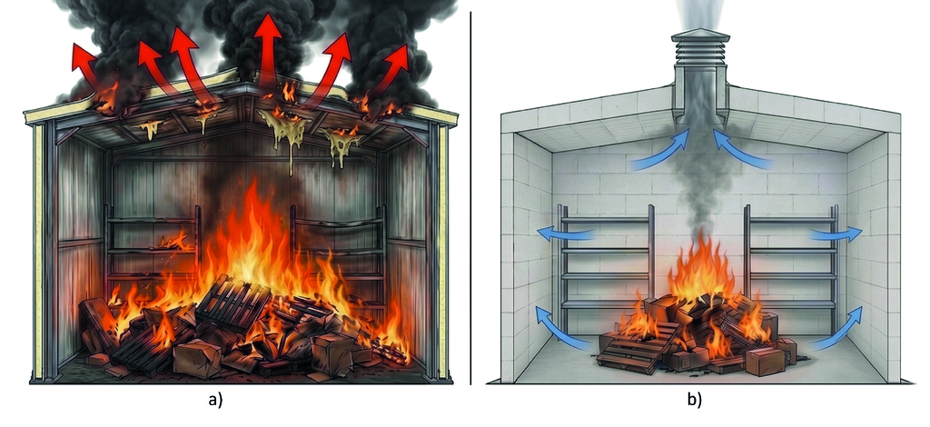
Solid AAC roof panels enhance the fire protection performance of the fire wall beyond the wall area itself. They prevent components of roof structures that have been damaged or melted during a fire from impairing the function of the fire wall. Furthermore, because AAC is non-combustible and does not produce burning droplets, it prevents molten roof insulation from flowing along the underside of the roof and bypassing the fire wall.
In addition, AAC roof systems can contribute to preventive fire and explosion protection, for example, by providing structural pressure-relief areas while simultaneously limiting fire spread through the solid roof construction. Figure 2 illustrates the development and spread of fire, as well as the occurrence of secondary fires, in a warehouse constructed using conventional construction and AAC wall and roof panels.
Protection against external fire spread
Fires do not always originate within a building. Fires that occur outside, such as those involving stored combustible materials or parked vehicles, may spread to the interior through the façade, bypassing internal fire walls. External walls constructed from AAC, which inherently provide the same fire resistance rating as the building's fire walls, offer effective protection against external fire exposure and help prevent fire penetration into the structure. Thus, these walls complement the overall fire protection system, which includes fire walls and fire-resistant roof constructions.
Doors and glazing
Door openings in fire walls are fitted with commercially available fire doors approved for installation in AAC prefabricated components (T 90-1 single-leaf up to 1.25 m × 2.50 m, T 90-2 double-leaf up to 3.00 m × 3.00 m) and require a minimum wall thickness of 175 mm. Fire-resistant glazing can be installed directly into AAC walls from AAC 4.5 and ≥ 175 mm thickness; in fire walls, the opening size of individual panes is limited to 1 m².
Verification of fire resistance
Verification is conducted either through fire testing or by providing normatively prescribed evidence. Classification tests follow the European test standards DIN EN 1364-1 9] for non-load-bearing walls, DIN EN 1365-1 [10] for load-bearing walls, and DIN EN 1363 [11] for general fire resistance testing requirements. Mechanical impact loading is evaluated according to DIN 4102-3 [12]. For standardized constructions, fire resistance classifications may be assigned in accordance with DIN 4102-4 without separate fire testing, provided that the specified boundary conditions are met.
Mechanical impact loading: the pendulum impact test
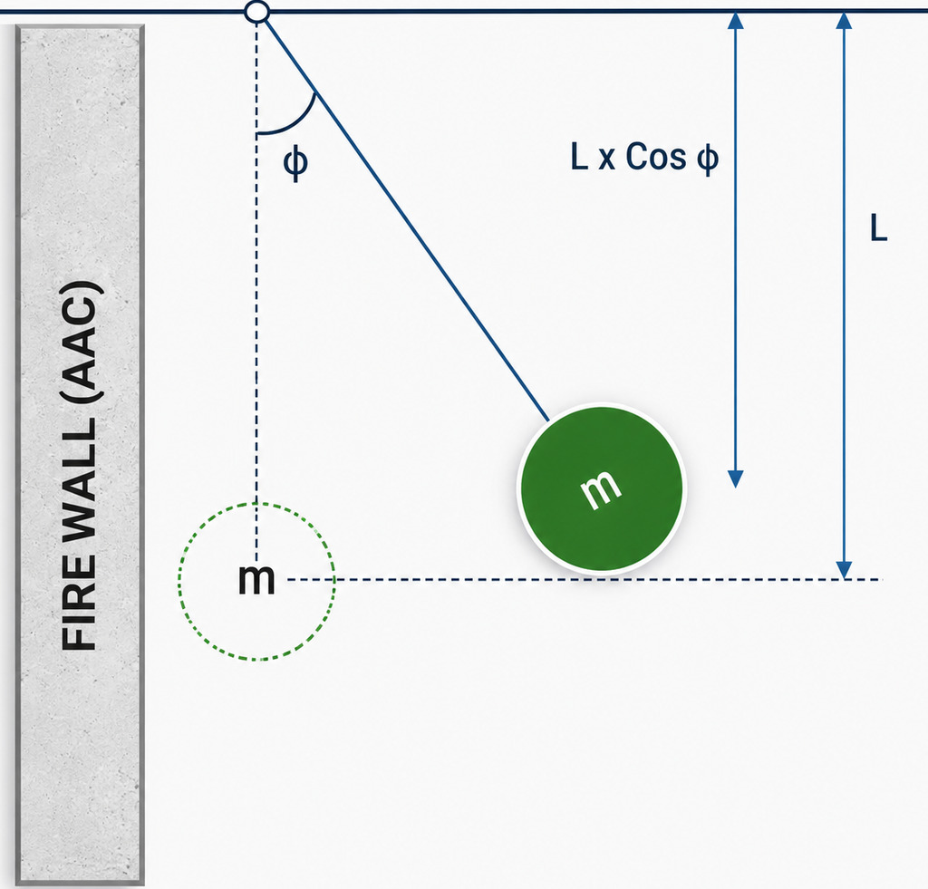
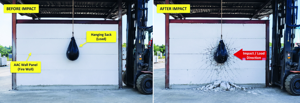
The distinguishing characteristic M sets a fire wall apart from a standard fire-resistant wall and is confirmed through a standardized pendulum impact test in accordance with DIN 4102-3. In this test, the specimen is mounted in front of the test rig and subjected to two impacts under the eccentric load p, as specified in Section 4.3.2 of DIN 4102-3, followed by a third impact under its own weight g, using a 200 kg lead shot bag. Each impact delivers an energy of 3,000 Nm to an area of approximately 400 cm². The impact is applied as a pendulum impact with a pendulum length of approximately 3 m on the side opposite the fire.
During and following the first two pendulum impact tests, the fire wall is required to retain its load-bearing capacity and overall structural stability under the additional imposed load, p. After the third impact, the wall must remain stable under its self-weight, g. In addition, the integrity of the fire compartmentation function must be maintained throughout and after all impact events. On the unexposed side, the average temperature rise relative to the initial temperature must not exceed 140 K, while the temperature increase at any individual measurement location must remain below 180 K. Compliance with these impact-resistance requirements must be demonstrated by means of the standardized test procedure or an equivalent approved performance assessment; analytical calculations alone cannot replace the required experimental verification.
Engineering-based determination of the optimal equivalent impact force
In practice, the question frequently arises as to whether an equivalent static load can represent the pendulum impact loading. Indeed, there is no generally accepted or normatively defined static equivalent load for this purpose. The impact event is inherently dynamic, and the resulting force history depends significantly on the contact duration, deformation characteristics, and stiffness of the overall system.
The impact velocity of the 200 kg pendulum can be derived from the impact energy using the principle of energy conservation:

If an example impact duration Δt is assumed for an approximate assessment, an average equivalent force results from the impulse-force relationship calculated as:
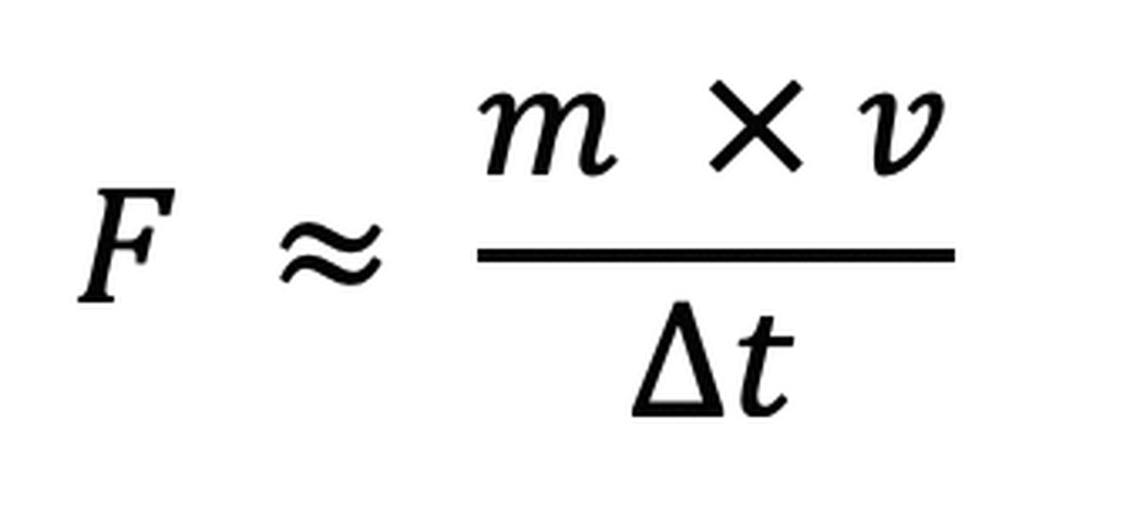
However, the impact duration is not a standardized parameter and is not specified as an input value for the pendulum impact test according to DIN 4102-3. Rather, it results from the dynamic interaction between the pendulum mass, the wall assembly, and the test configuration. Consequently, the impact force is highly system-dependent and cannot be uniquely determined from the prescribed impact energy alone.
When a lead shot bag is used as the impact body, substantially greater impact damping can be expected than with a rigid impactor. This damping effect arises from three principal mechanisms. First, the bag deforms upon impact and conforms to the wall surface, increasing the distance and time over which the kinetic energy is transferred. As a result, the energy is introduced into the component more gradually rather than as an abrupt impulse. Second, the individual lead pellets move relative to one another and rearrange during impact. Frictional effects and internal redistribution processes dissipate in part of the kinetic energy as heat and deformation energy. Third, the overall deformability of the lead shot bag increases the duration of the impact event. Since the average impact force is inversely proportional to the contact duration then:
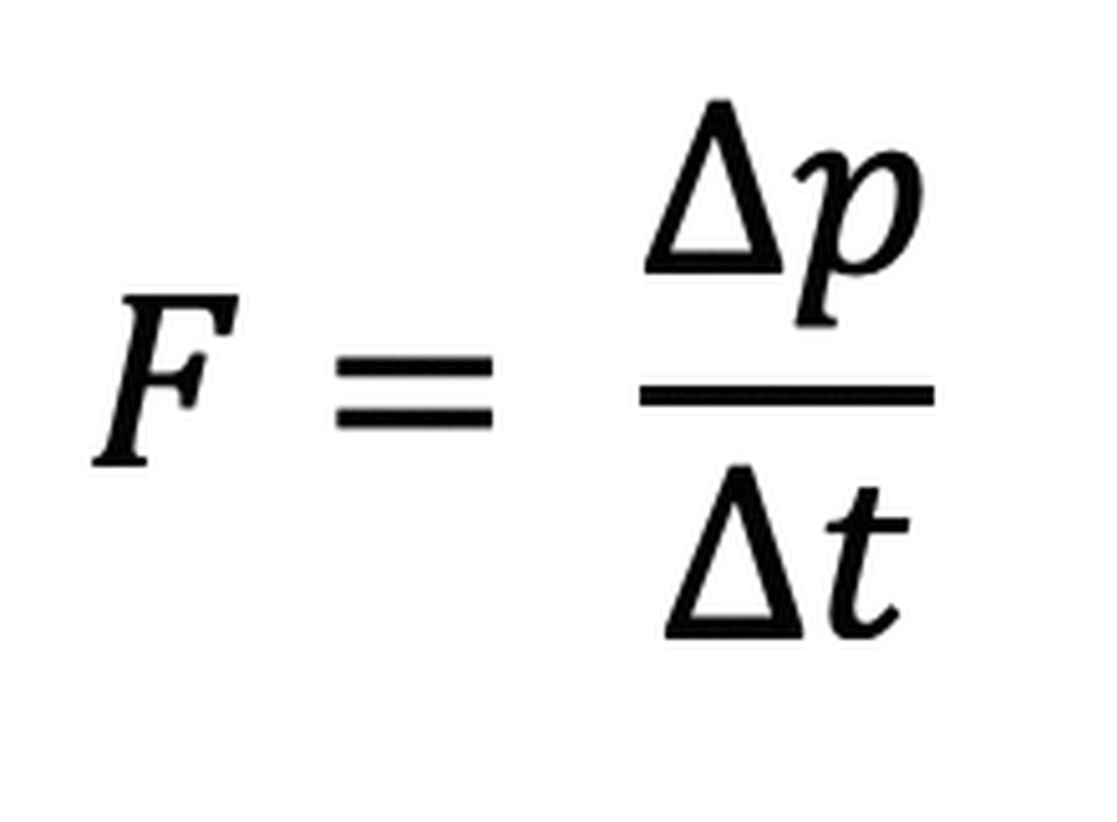
An increase in impact duration results in a corresponding reduction in the average impact force.
For engineering-based estimations, an impact duration in the range of approximately 0.10 to 0.15 s may therefore be considered a reasonable modeling assumption. This range is not arbitrary but reflects the expected variation in the damping behavior of the lead shot bag. An impact duration of Δt=0.10 s represents a relatively short contact time and thus a comparatively low degree of damping. It therefore yields the higher equivalent force and may be regarded as the more conservative assumption. By contrast, Δt=0.15 s reflects a greater degree of damping resulting from bag deformation and pellet rearrangement, leading to a lower equivalent force. Together, these values define a plausible range bounded by a conservative upper estimate and a lower estimate that more closely reflects the expected energy dissipation characteristics of the impact body.
It should be emphasized that the values presented herein represent simplified engineering approximations intended solely to facilitate interpretation of the impact loading. They do not constitute a valid method of compliance assessment and cannot replace the experimental verification procedure specified in DIN 4102-3, where performance is demonstrated by standardized testing under fire and impact conditions rather than by the application of an equivalent static load. However, these estimates are valuable for scientific investigations and numerical simulations, as they support the assessment of load-bearing behavior, energy absorption capacity, deformation response, and safety margins of various wall constructions.
Table 4: Engineering-based comparative values for different assumed impact durations (not a normative design value)
Assumed impact duration Δt | Calculated average equivalent force F |
0.10 s (conservative) | ≈ 11 kN |
0.15 s (stronger damping) | ≈ 7.3 kN |
Table 4 presents engineering-based comparative impact load values calculated for various assumed impact durations. This table demonstrates how impact duration affects the estimated impact force and establishes a consistent basis for comparing different impact scenarios. The calculated forces, approximately 11 kN and 7.3 kN, serve as engineering estimates to indicate the order of magnitude of dynamic loading. These values are not normatively defined design parameters. The extent to which either value represents actual conditions is determined by the dynamic characteristics of the overall system, including the pendulum body, the wall, and its support conditions. In the absence of supporting measurements, this cannot be determined conclusively.
Special application: fire walls in data centers
Data centers impose exceptionally stringent requirements on structural fire protection. In contrast to many other building types, the primary objective extends beyond occupant safety to include the safeguarding of high-value assets and the continuity of critical IT operations. Smoke or soot contamination, even without direct flame exposure, can irreversibly damage servers, network equipment, and cabling in adjacent areas, leading to economic losses that may significantly exceed the physical fire damage.
To mitigate these risks, data centers are generally divided into distinct fire compartments, separating server halls, UPS and battery rooms, emergency power systems (including diesel generators and fuel storage), as well as cable shafts and service ducts. In Germany, operators frequently adhere to industry guidelines such as VdS 2007 [13], which recommend or mandate fire-resistant compartmentation between safety-critical technical areas. Similar requirements are found in international standards and best-practice frameworks, including TIA-942 [14] and EN 50600 [15].
Given these requirements, AAC fire walls offer a highly suitable solution for fire compartmentation in data centers. Because it is classified as a Class A1 non-combustible building material, it does not produce smoke or toxic or corrosive combustion gases when exposed to fire. This property limits secondary damage to sensitive electronic equipment, which in data centers frequently results in greater economic losses than the direct effects of fire.
AAC's high thermal insulation capacity minimizes heat transfer to adjacent compartments, thereby protecting server racks, cabling systems, and cooling infrastructure during extended fire exposure in neighboring compartments. Its resistance to mechanical impact (classification M) is especially relevant where fire walls border areas with internal vehicle traffic or equipment-handling activities, including battery replacement, emergency power system maintenance, or material transport within technical service zones. As a monolithic and homogeneous construction material, AAC eliminates the need for additional combustible insulation layers or protective coatings, thereby reducing potential weak points, interfaces, and construction details that could compromise fire compartmentation integrity. The growing adoption of lithium-ion batteries in UPS installations underscores the necessity for robust passive fire protection measures. Due to the challenges posed by thermal runaway events, passive compartmentation solutions remain effective regardless of active fire suppression systems and continue to provide protection during system failure, maintenance, or inspection.
Conclusion
AAC is a mineral-based construction material that combines non-combustibility, dimensional stability at high temperatures, good thermal insulation properties, and smoke-tightness. It therefore meets both the thermal and mechanical performance requirements for fire walls as specified in DIN 4102 and DIN EN 13501. The extra classification M, which confirms resistance to mechanical impact through the standard pendulum impact test defined in DIN 4102-3, remains an essential part of the fire wall's qualification. Although analytical assessments may support engineering evaluations, they cannot take the place of the experimental verification required by the standard. When used together with AAC roof panels, it is possible to obtain a mostly homogeneous and completely non-combustible building envelope. This complete system ensures reliable fire compartmentation, prevents the spread of fire between adjacent compartments, and helps to protect against external fire exposure and the spread of fire.
For data center designers, the combined benefits of non-combustibility, superior thermal insulation, and high mechanical impact resistance directly address the stringent performance and safety requirements of this highly sensitive and economically critical building type. These characteristics contribute to enhanced fire resilience, improved energy efficiency, and greater protection of critical infrastructure and operational continuity. Consequently, AAC wall and roof panels offer a comprehensive solution that meets both safety and performance objectives, making them a particularly suitable and effective construction system for data center applications.
Disclaimer
The visualizations shown in this article were created with the assistance of AI tools. As a result, they may occasionally include minor artifacts, inaccuracies, or unrealistic representations.
References
[1] DIN 4102-1: Fire behaviour of building materials and building components. Part 1: Building materials, requirements and tests; (1998).
[2] DIN EN 13501-1: Fire classification of construction products and building elements. Part 1: Classification using reaction-to-fire test data; (2019).
[3] Musterbauordnung (MBO): German Model Building Code; ARGEBAU (2024).
[4] DIN EN 13501-2: Fire classification of construction products and building elements. Part 2: Classification using fire resistance test data; (2023).
[5] Beton Brandschutz-Handbuch; Prüfbericht 97-U-040; CTICM (1997).
[6] Certificate No. MPA-BS A05/001, MPA Braunschweig. Materialprüfanstalt für das Bauwesen Braunschweig (2023).
[7] Industriebaurichtlinie (IndBauRL): Industrial Building Directive. DIBt (2019).
[8] DIN 4102-4: Fire behaviour of building materials and building components. Part 4: Classified building materials and components; (2025).
[9] DIN EN 1364-1: Fire resistance tests for non-loadbearing elements. Part 1: Walls; (2015).
[10] DIN EN 1365-1: Fire resistance tests for loadbearing elements. Part 1: Walls; 2013).
[11] DIN EN 1363-1: Fire resistance tests. Part 1: General requirements; (2020).
[12] DIN 4102-3: Fire behaviour of building materials and building components. Fire walls and non-loadbearing external walls; (1977).
[13] VdS 2007: Fire protection for industrial buildings; (2007).
[14] ANSI/TIA-942: Telecommunications infrastructure standard for data centers; TIA (2024).
[15] EN 50600: Information technology. Data centre facilities and infrastructures; CENELEC (2022).