Application & Construction
Masonry structures
Full-scale studies of stiffening walls made of autoclaved aerated concrete
Loading...
Krzysztof Grzyb is researcher at the Department of Building Structures of the Silesian University of Technology with experience in masonry and reinforced concrete structures research. Author of publications regarding autoclaved aerated concrete, stiffening and confined masonry walls, and reinforced concrete slab tests. Passionate about renovating historic buildings and actively dealing with the structural aspect of intervention, preservation and repair works. Co-author of projects and numerous technical expertise encompassing reinforced concrete, prestressed, steel, wooden, and masonry structures. krzysztof.grzyb@polsl.pl

Radosław Jasiński is PhD DSc CEng Associate Professor of the Silesian University of Technology, Head of Laboratory of Civil Engineerieng Faculty. A graduate of the Faculty of Civil Engineering, Silesian University of Technology in Gliwice, specializing in Bridges. His scientific interest are: masonry structures, reinforced concrete structures, diagnosis of structures (NDT, MDT), numerical modelling of structures. He is an author of over 350 books, handbook, papers in technical journals and at national and international conferences. Since 2010 he is a member of the International Masonry Society. radoslaw.jasinski@polsl.pl
Stiffening elements in buildings provide the safe transfer of horizontal forces to the foundation. Lateral impacts are caused by wind, but also by uneven subsidence or negative effects of mining activities. Stiffening masonry walls are designed to ensure the global stiffness of the building structure, limit the horizontal displacement of the structure and guarantee the comfort of use.
The current design trend is to reduce wall thicknesses. Engineers most often verify the load capacity of walls due to loads acting mainly vertically but omit verification of walls for shear. Such design is not only dangerous, but it can cause serviceability problems when cracks appear on the walls. One of the drawbacks of commonly erected stiffening walls made of autoclaved aerated concrete is the appearance of cracks even at a low level of horizontal loads.
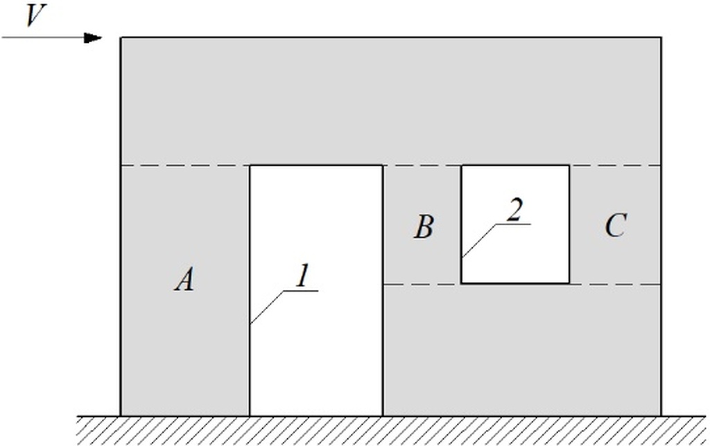
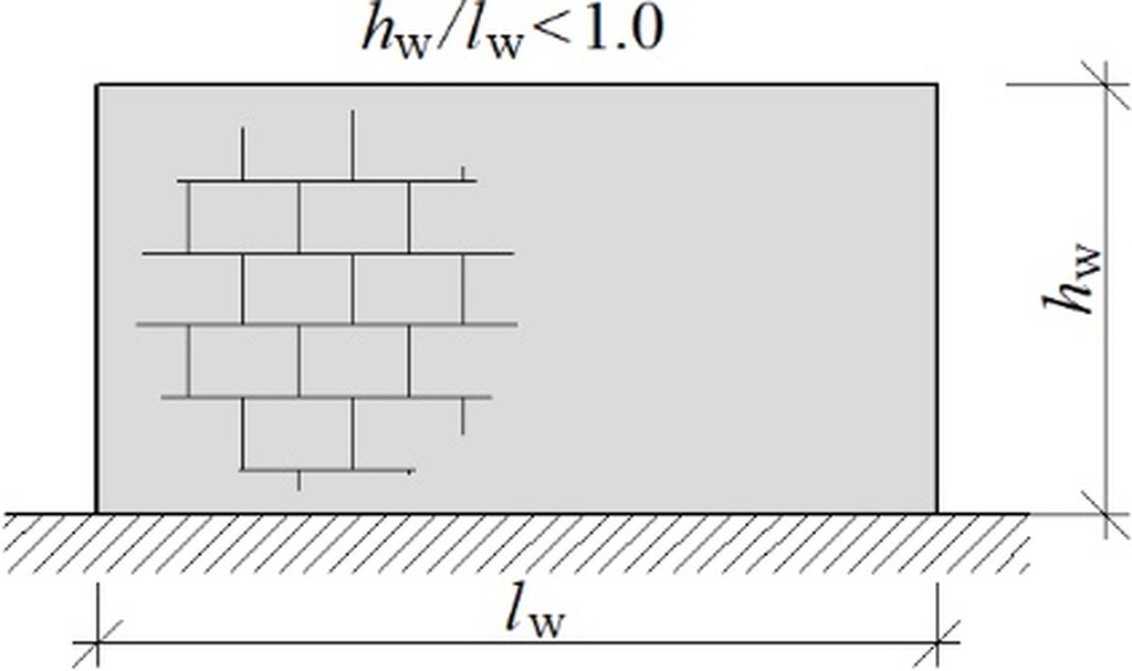
The term stiffening wall is used interchangeably with the shear wall. A wall without any openings is called a solid wall and a wall with openings is described as a perforated one (Fig. 1), according to Canadian regulation [1]. Moreover, shear walls can be classified by aspect ratio which means the relationship between the height (hw) and length (lw) of the stiffening wall. The value of this coefficient is essential because it informs about what deformations of the wall are dominant - flexural or shear.
If the aspect ratio value is smaller than one, then shear deformations dominate (Fig. 2a). The value of an aspect ratio exceeding 1 suggests that the contribution of flexural deformations of the stiffening wall is significant (Fig. 2b).

The commonness of stiffening walls and their crucial role in a building does not coincide with the theoretical and experimental recognition of their behavior. Research gaps include the effect of openings on the stiffness of the wall, redistribution of internal forces, and taking into account the rotation of the building resulting from the different stiffness and geometry of the stiffening structural elements.
Most shear masonry research is cyclic loading tests [2-5] and monotonic load tests are rare. One of the few studies of shear walls loaded with static load is included in [6]. The influence of confining elements and different types of reinforcement on the behavior of shear walls is determined in [7]. The results of the structural work of dry joint masonry under the different compressive normal stresses and horizontal loads are described in [8].
Although the study of wall models provided knowledge about the behavior of a single wall, there is a lack of full-scale studies of buildings. Research on building models enables the recognition of the spatial work of the structure and verification of the torsion effect of the building with asymmetric distribution of stiffening elements. This article presents the latest results of an extensive study conducted at the Silesian University of Technology as part of the program of testing masonry stiffening walls.
Materials and methods
Full-scale research model
The full-scale model of the building was made of masonry units made of autoclaved aerated concrete (AAC). The width of a single block is 180 mm, the length is 590 mm and the height is 240 mm. The density of masonry units is 600 kg/m3. Walls are erected as a thin joint masonry structure with filled bed joints and unfilled head joints. The vertical connections between elements are tongue and groove – Fig. 3. The mortar class is M5.
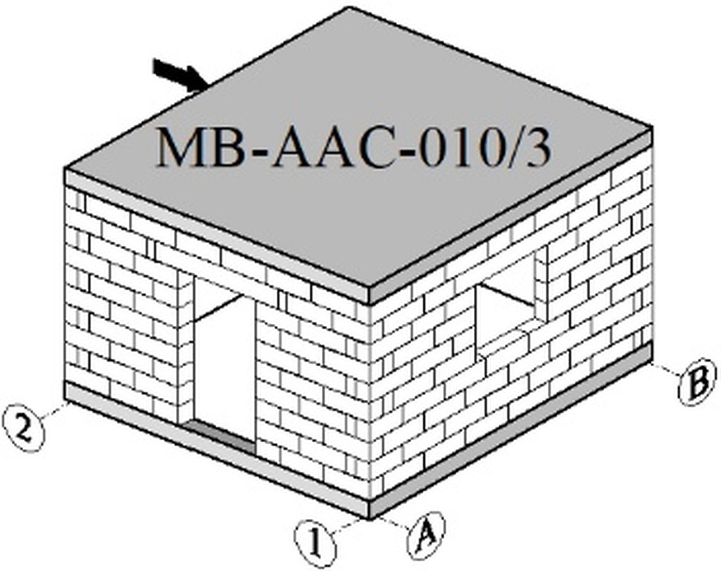
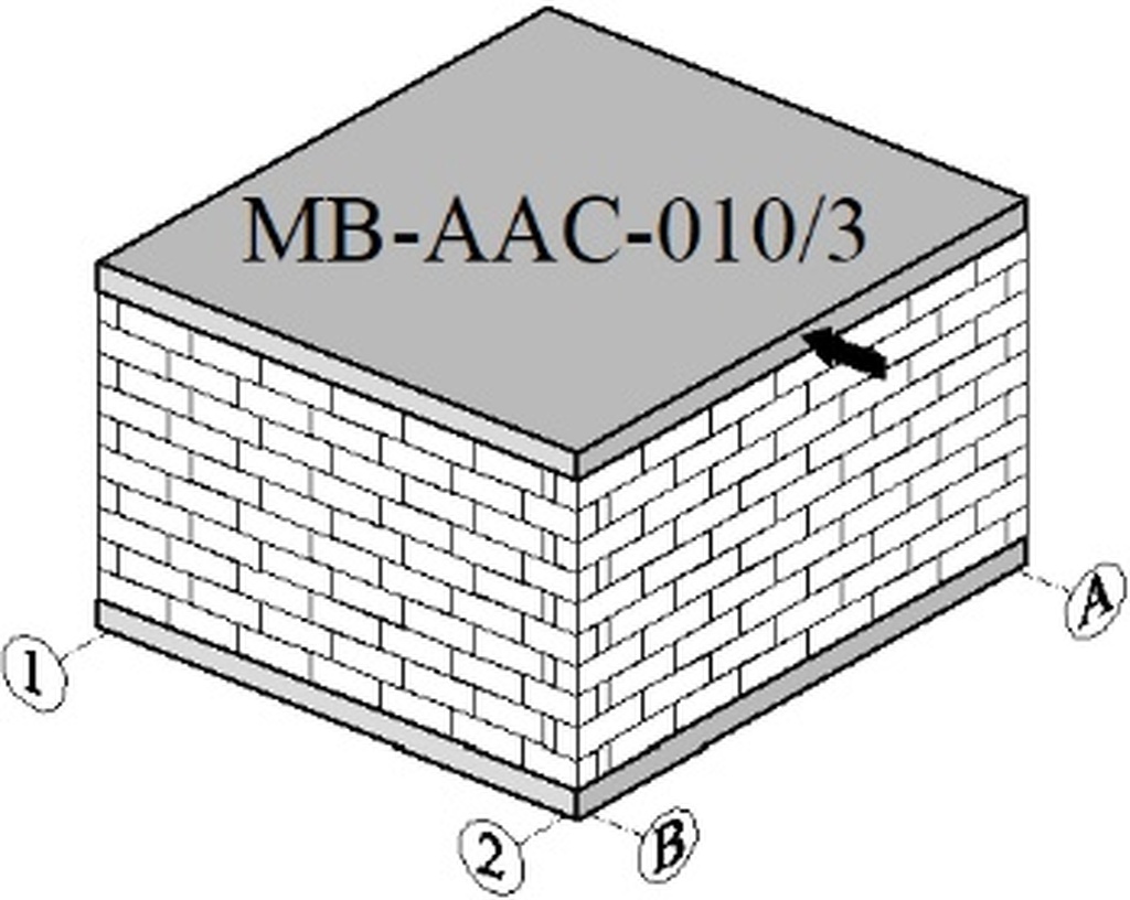
The building model was made on a square plan with dimensions of 4.0x4.0 m. The thickness of the walls corresponds to the thickness of the masonry unit and is equal to 180 mm. The total height of the model is 2.85 m. The ceiling was made in a partly precast structure as slab panels monolithized with a concrete overlay. The slab was designed to be a rigid diaphragm in its plane.
The stiffening walls are marked with the letters A and B, and the perpendicular walls with the numbers 1 and 2. A door opening of dimensions 1.0x1.92 m is made in wall A and a window opening 1.0x1.0 m is made in perpendicular wall 1. The model of the tested building is shown in Fig 4.

Test stand
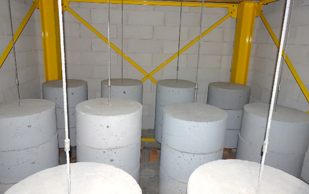
The own stand for testing stiffening walls on full-scale models was designed. The building was fixed on a strong floor. A steel column with a brace was located next to the model. The horizontal force was induced by a hydraulic actuator of the 1000 kN range supported by steel construction mounted on the steel column – Fig. 5. Concrete weights suspended from the slab were used to induce initial compressive stresses sc = 46.26 kN/m2 = 0.05 N/mm2 corresponding to dead weight and live weight. A total of 36 weights each of 204 kg were suspended – Fig. 6.

Measuring methods
Linear variable differential transformer (LVDT) sensors were used for displacement measurements. For this purpose, rectangular measuring bases were mounted on the walls – Fig. 7. LVDT sensors with a measuring range of 20 mm (PJX-20) were mounted on the diagonals and LVDT sensors with a range of 10 mm (PJX-10) on the vertical and horizontal frames. The resolution of the indications was 0.002 mm. Thanks to the mathematical rules and the results from the sensors, it was possible to calculate the shear strain angle in the elastic range and the deformation angle in the non-linear range.

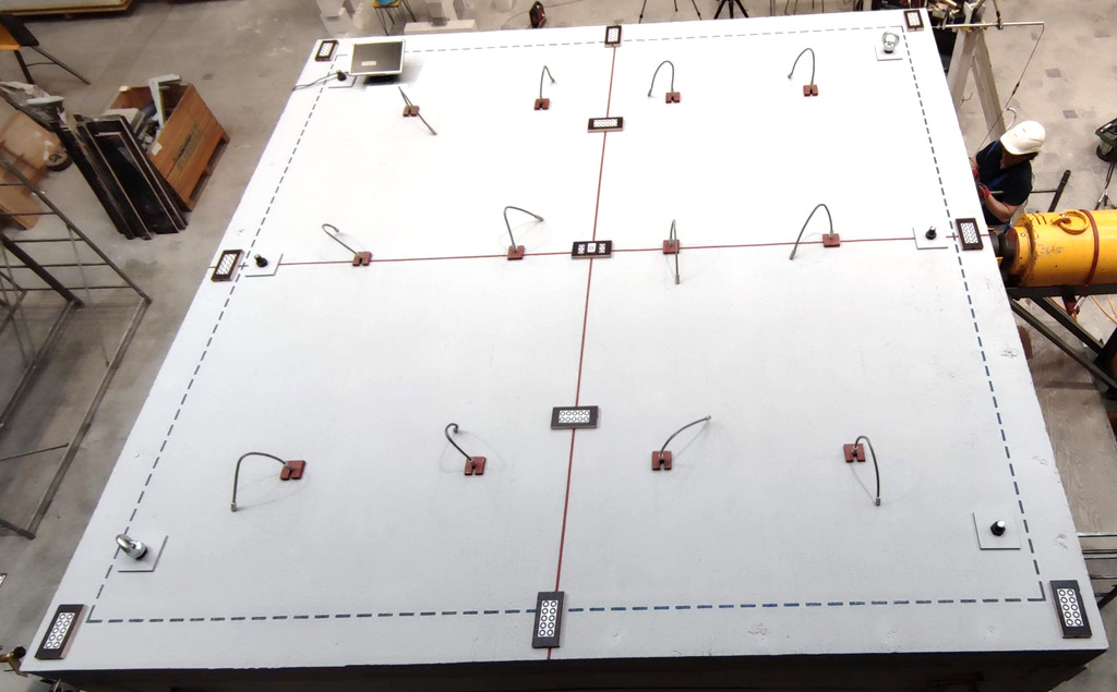
During the test, the displacements of the slab were also measured. On the floor were placed benchmarks for digital image correlation – Fig. 8. A digital camera was suspended over the building model, and the photos were taken sequentially during the loading process. The resolution of DIC indications was 0.01% and the measurement of the horizontal force was made with a force gauge.
Test results
The behavior of stiffening walls
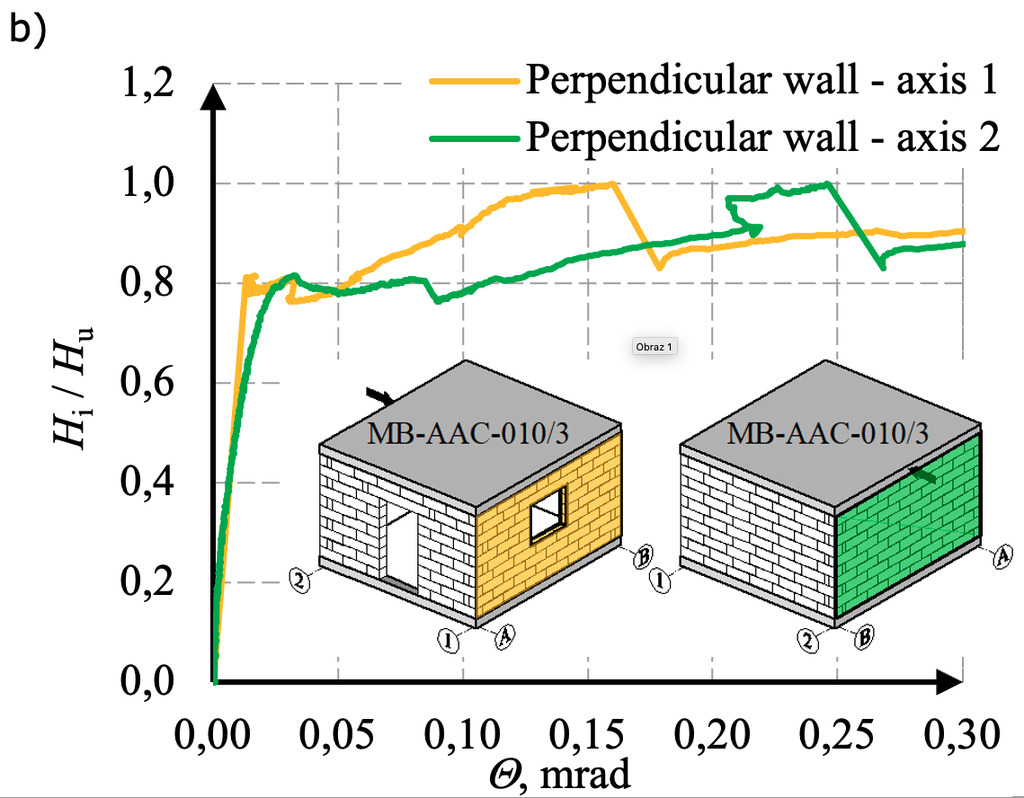
The results are presented in the graphs of the normalized horizontal force (Hi/Hu) to the shear strain angle Θi (elastic range) or the shear deformation angle (nonlinear range). The behavior of the stiffening walls A and B are shown in Fig. 9a, and the behavior of perpendicular walls 1 and 2 in Fig. 9b.

Moreover, the values of horizontal displacements were calculated based on the known values of shear deformation angles following the formula (1). The results are presented in the graphs of the normalized horizontal force to the horizontal displacements in Fig. 10.

in which:
ui – horizontal displacement in the direction x along to load (ux) or direction y perpendicular to load (uy),
Θi – shear strain angle in linear phase and shear formation angle in non-linear phase,
h – the height of the model and equal h = 2.63 m (the height of the building without the lower reinforced ring beam).
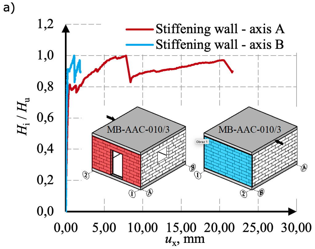
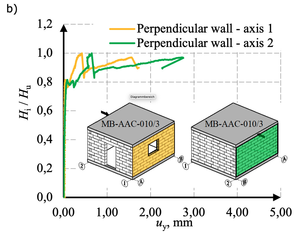
The maximum horizontal force in the tests was 74.1 kN and the maximum horizontal displacements of the stiffening wall A reached a value of over 21 mm. Horizontal displacements of perpendicular walls 1 and 2 were significantly smaller and amounted to about 1-2mm.
Crack propagation and crack pattern
Progressing cracks on the walls of the building model were marked during the test. Figures 11 and 12 present the crack pattern of the tested model.


The initiation of cracks takes place in the tensile corner of the opening – stiffening wall A (Fig. 11). Diagonal cracks appeared as the building was loaded. In solid stiffening wall B, the diagonal crack divided the wall into two parts and after reaching the load capacity of the wall, the part above the crack undergoes significant horizontal displacements (sliding failure). Due to the relatively small initial compressive stresses, the cracks occurred mainly between the joints. In perpendicular walls observed smaller areas of damage (Fig. 12). There is a horizontal crack in half the height of wall 2 from the side of the applied load. This damage is the result of tensile and lifting of the wall. Damage to the structure results in the degradation of the wall stiffness and the increase of horizontal displacements.
Torsion of the building effect
The different stiffness of the walls causes the building to twist. The analysis of displacement vectors showed that in the initial phase when the stiffness of the building is the highest, the building rotates. As the load increases, the walls crack, and the internal forces redistribute. The equalization of internal forces between the walls makes the rotation give way to the translation of the building.
In the final stage of the test, the rotation is marginal, and the horizontal displacement, consistent with the action of the lateral load, dominates (translation with little rotation).
Discussion
The analysis of the dependencies shown in section 3.1 enables distinguishing the behavior phases of stiffening walls. For the stiffening wall with a door opening (wall A), the four stages can be designated – the initial phase, the elastic phase, the nonlinear phase and the post-peak residual one. There is no initial phase in walls without openings (wall B).
Table 1: The values of horizontal forces and deformation angles based on test results
Wall | Initial phase | Elastic phase | Nonlinear phase | Post-peak residual phase | ||||
Hcr,1, | Θcr,1, | Hcr, | Θcr, | Hu, | Θu, | Hres, | Θres, | |
A | 20.768 | 0.034 | 60.385 | 0.202 | 74.048 | 2.967 | 61.455 | 3.202 |
B | - | - | 67.631 | 0.098 | 0.410 | 61.455 | 0.436 | |
The characteristic values of the horizontal force and the corresponding shear deformation angles are summarized in Table 1. Based on the empirical method of determining the stiffness of the stiffening walls [9], the stiffness of walls A and B was calculated – Table 2. Using the proportion between the shear deformation angles, the horizontal forces acting on the walls were calculated – Table 3.
Table 2: Stiffness of stiffening walls based on the test
Wall | Initial phase | Elastic phase | Nonlinear phase | Post-peak residual phase |
Kcr,1, | Kcr, | Ku, | Kres, | |
A | 254.6 | 124.4 | 10.4 | 8.0 |
B | - | 287.4 | 75.3 | 58.7 |
Table 3: Horizontal forces acting on stiffening walls
Wall | Elastic phase | Nonlinear phase | Post-peak residual phase |
Hcr, | Hu, | Hres, | |
A | 32.6 | 37.0 | 30.7 |
B | 31.4 | 37.0 | 30.7 |
When the horizontal load increases, subsequent cracks cause significant degradation in wall stiffness (Table 2). After reaching the maximum force, the forces acting on the walls equalize due to the redistribution of internal forces (Table 3). In the residual phase, horizontal displacements increase rapidly (translation).
Conclusions
Stiffening walls are essential structural elements whose role is to safely transfer horizontal forces to the foundation. Experimental recognition of shear masonry under monotonic static load is still marginal. A full-scale study of a building model made of autoclaved aerated concrete was carried out at the Silesian University of Technology. Based on research, it was found that:
· the initiation of cracks takes place in the tensile corner of the opening,
· progressive cracking of masonry walls causes significant degradation of their stiffness,
· the behavior of stiffening walls with openings can be described by four phases (the initial phase, the elastic phase, the nonlinear phase and the post-peak residual phase),
· there is no initial phase in solid stiffening walls, the behavior can be designated in three stages (the elastic phase, the nonlinear phase and the post-peak residual phase),
· in the initial phase when the stiffness of the building is the highest, the building tends to rotate,
· in the residual phase, the rotation is marginal, and the horizontal displacement dominates (translation with little rotation).
The presented results are part of an extensive research program of stiffening walls conducted by the authors of the paper.
Acknowledgement
Krzysztof Grzyb is a holder of a European Unionscholarship through the European Social Fund, grant InterPOWER (POWR.03.05.00-00-Z305).
The authors would like to thank Konbet and Solbet S.A. companies for their valuable suggestions and the delivery of masonry units, mortar, floor slabs, and beams elements used to prepare test models and perform tests.
This article (as full version) appeared in its original form in the proceedings of ICAAC 2023 (7th International Conference on Autoclaved Aerated Concrete): Grzyb K, Jasiński R. Full-scale studies of stiffening walls made of autoclaved aerated concrete. ce papers.2023;6;135-141. https://doi.org/10.1002/cepa.1973
References
[1] Canadian Standards Associations CSA S304-14.
[2] Da Porto, F.; Guidi, G.; Garbin, E.; Modena, C. (2010) In-Plane Behavior of Clay Masonry Walls: Experimental Testing and Finite-Element Modeling. Journal of Structural Engineering, 136, pp. 1379-1392.
[3] Calderón, S.; Sandoval, C.; Arnau, O. (2017) Shear response of partially-grouted reinforced masonry walls with a central opening: Testing and detailed micro-modelling. Materials & Design, 118, pp. 122-137
[4] Minaie, E.; Moon, FL.; Hamid, AA. (2014) Nonlinear finite element modeling of reinforced masonry shear walls for bidi-rectional loading response. Finite Elements in Analysis and Design, 88, pp. 44 - 53.
[5] Sajid, HU.; Ashraf, M.; Ali, Q.; Sajid, SH. (2018) Effects of vertical stresses and flanges on seismic behavior of unreinforced brick masonry. Engineering Structures, 155, pp. 394 – 409.
[6] Jasiński, R. (2017) Research and modelling of masonry shear walls. PhD DsC Thesis (in polish). Silesian University of Technology.
[7] Jasiński, R. (2018) Comparisons of confined and different types of reinforcement on the behavior of masonry shear walls. Ce/papers Ernst & Son, 2, pp. 353 – 365.
[8] Lourenço, PB.; Oliveira, DV.; Roca, P.; Orduña, A. (2005) Dry Joint Stone Masonry Walls Subjected to In-Plane Combined Loading. Journal of Structural Engineering, 131, pp. 1665 – 1673.
[9] Grzyb, K.; Jasiński, R. (2022) Research on the Behavior of Stiffening Walls in Single-Storey Buildings Made of Autoclaved Aerated Concrete (AAC) Masonry Units. Materials, 15, pp.1 – 25.