Application & Construction
Investigations from Poland
Safety of reinforced AAC lintels
Loading...
Łukasz Drobiec, PhD DSc CEng, Assistant Professor at Department of Building Structures, Silesian University of Technology, Gliwice, Poland. A graduate of the Faculty of Civil Engineering, Silesian University of Technology in Gliwice, specializing in Construction and Engineering. Since 2004, he has been employed at the Department of Structural Engineering, Silesian University of Technology, now an assistant professor with post-doctoral thesis and head of Department.
He is the author and co-author of over 300 publications, including 14 books, and a lot of articles in foreign and domestic journals, chapters in books and papers delivered at national and international conferences. He is a member of the PZITB Scientific Committee, Gliwice PZITB Branch, and the International Masonry Society. He was granted 9 individual or group awards by the Vice-Chancellor of the Silesian University of Technology for organizational activities and achievements in research and academic work, and two awards of the Vice-Chancellor of the Katowice Technical University.

Radosław Jasiński is Prof. PhD DSc CEng Full Professor of the Silesian University of Technology, Head of Laboratory of Civil Engineerieng Faculty. A graduate of the Faculty of Civil Engineering, Silesian University of Technology in Gliwice, specializing in Bridges. His scientific interest are: masonry structures, reinforced concrete structures, diagnosis of structures (NDT, MDT), numerical modelling of structures. He is an author of over 350 publication, handbook (17), patents (2), papers in technical journals and at national and international conferences. Winner of numerous awards from the Rector of the Silesian University of Technology (20) and the Minister of Construction (2) as well as the prestigious S. Bryła Award of the Polish Association of Construction Engineers and Technicians - PZITB (2019). Since 2010 he is a member of the International Masonry Society.

Wojciech Mazur is PhD Eng, Assistant Professor at the Department of Building Structures, Silesian University of Technology, Gliwice, Poland. Since 2017, he has been employed at the Department of Building Structures, Silesian University of Technology. He is the author and co-author of over 60 publications, including a lot of articles in foreign and domestic journals, chapters in books and papers delivered at national and international conferences. He also has an extensive research experience, primarily focusing on masonry and reinforced concrete structures.
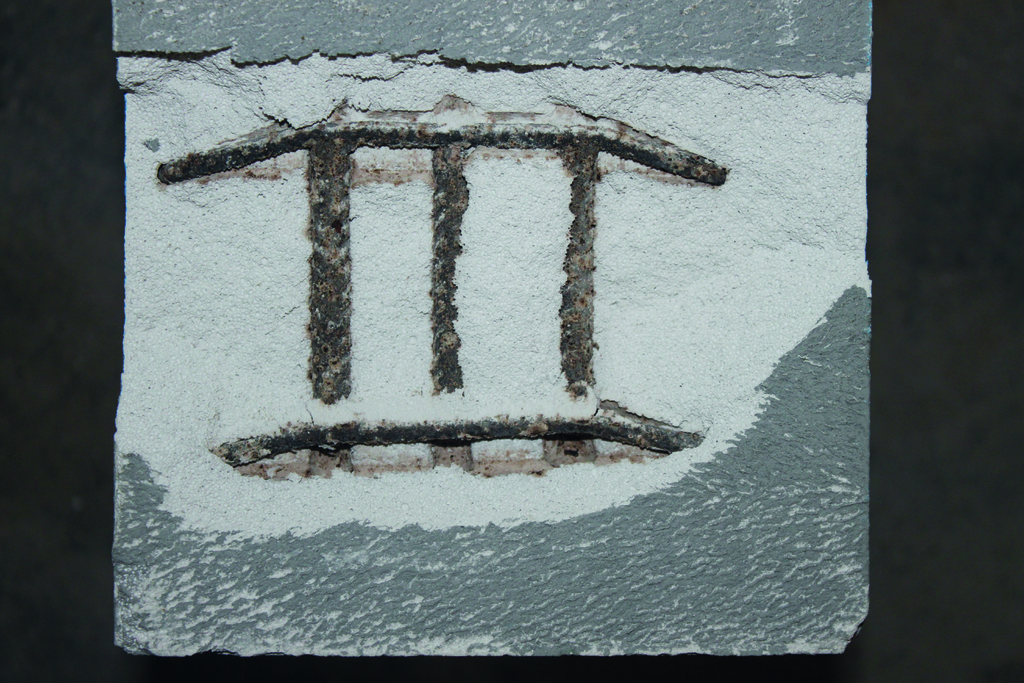
Safety issues resulting from the ageing of reinforced AAC elements were first reported in the 1980s and 1990s, when the roof of an English building collapsed [1, 2]. A report published by the Building Research Facilities in 1996 demonstrated that reinforced floor panels often exhibited cracking (Fig. 1) and deflections. It recommended that any damaged panels should be inspected annually and those without damage should be visually inspected every five years. In 2021 and 2022, new guidelines were issued in the UK for the maintenance of reinforced AAC elements. In line with those recommendations, a facility may be used safely if the condition of reinforced AAC elements does not exhibit any damage classified as critical. However, in the summer of 2023, a reinforced roof element which had been considered to pose a low risk collapsed. Therefore 104 schools were closed in the UK in September 2023, as they were considered to be potentially dangerous. This has sparked a discussion on the safety of reinforced AAC masonry structures across Europe. In Poland, reinforced AAC lintels are the most common, while floor and roof slabs are much less popular. This article discusses the range of lintels available on the Polish market and describes the results of tests conducted at the Silesian University of Technology. The test results were used as a basis to conduct a reliability analysis of a reinforced AAC lintel interacting with masonry and a reinforced concrete ring beam.
((FIG.1))
Reinforced lintels available on the Polish market
Several Polish manufacturers of AAC offer reinforced floor slabs [3] and reinforced lintels in addition to masonry elements. Two types of lintels can be distinguished. These are composite and self-supporting lintels. Besides dimensions, the significant parameters of lintels include load capacity, minimum support length and proper placement of the tensile reinforcement.
Technical materials [4] state that composite lintels are manufactured with a height of 12.4 cm, width of 11.5 or 17.5 cm and length of 125 and 150-300 cm (every 50 cm) and support length of 15 to 25 cm. Composite lintels are designed for spanning openings with a maximum width of 250 cm. Single, double or triple composite lintels are installed to match the thickness of the masonry. Reinforcement is composed of two flat ladder-shaped reinforcement frames, in which the longitudinal rods are welded to the cross-rods. A lintel (spanning an opening of more than 110 cm in width) needs to be supported in the middle of its span during construction and achieves its load capacity only after the masonry constructed above the lintel has achieved its full strength. Self-supporting lintels of reinforced AAC are 24.9 cm high and make it possible to span window and door openings with a maximum width of 175 cm. The width of lintels is 20, 24, 30 or 36.5 cm and their length is 130, 150, 175, 200 or 225 cm with a minimum support length of 19.5 or 24.5 cm. The reinforcement of lintels is composed of smooth bars welded to each other. The maximum uniform design load is 13 to 23 kN/m. Lintels are made of AAC with a density class of 550 kg/m3 and compressive strength of fB= 4 N/mm2.
According to [5], the minimum support length is 20 cm for lintels that span openings whose width does not exceed 100 cm and 25 cm for lintels spanning wider openings. Lintels can be 24.9 cm high, 12, 15 or 20 cm wide and 120, 140, 170, 200 or 230 cm long, making it possible to span an opening of a maximum width of 175 cm. The load capacity beyond the dead load is 4.4 kN/m to 21 kN/m. Composite lintels are 12.4 cm high, 12, 15 or 20 cm wide and 120, 140, 170, 200, 230, 260 or 300 cm long, making it possible to span an opening of a maximum width of 250 cm. Lintels require installation support with a spacing of 75 cm. Composite lintels [6] are 12.5 cm high, 11.5 or 17.5 wide and 125, 150, 200, 250 or 300 cm long, making it possible to span an opening with a maximum width of 277 cm, while maintaining a minimum support length of 11.5 cm. The permissible characteristic load (beyond the dead load of the lintel and masonry) is 1.01 to 23.59 kN/m for a masonry height of 12.5 to 75 cm.
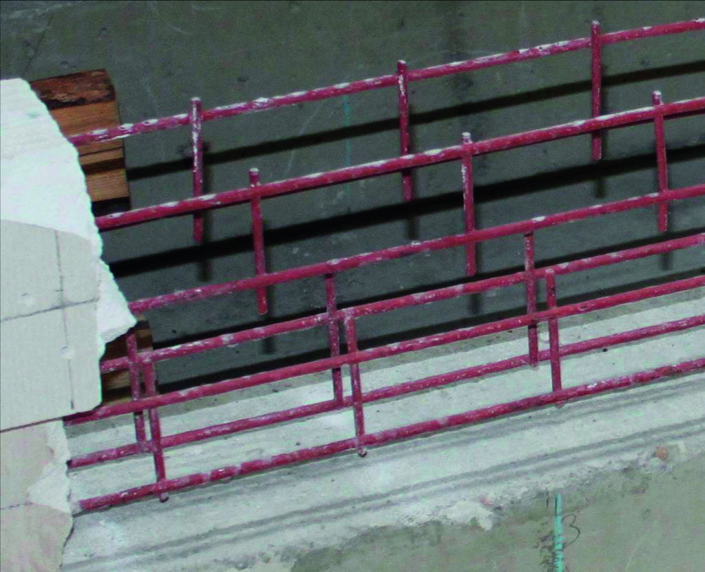
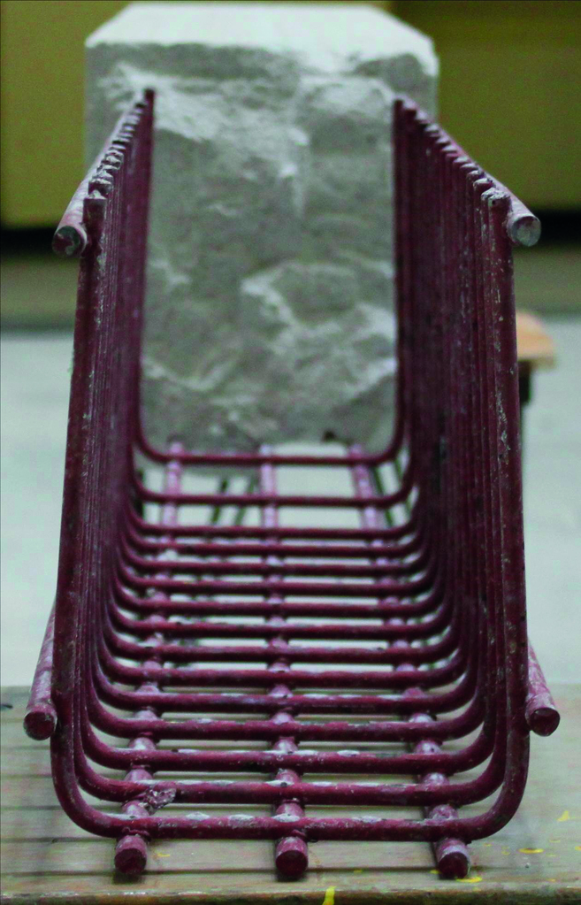
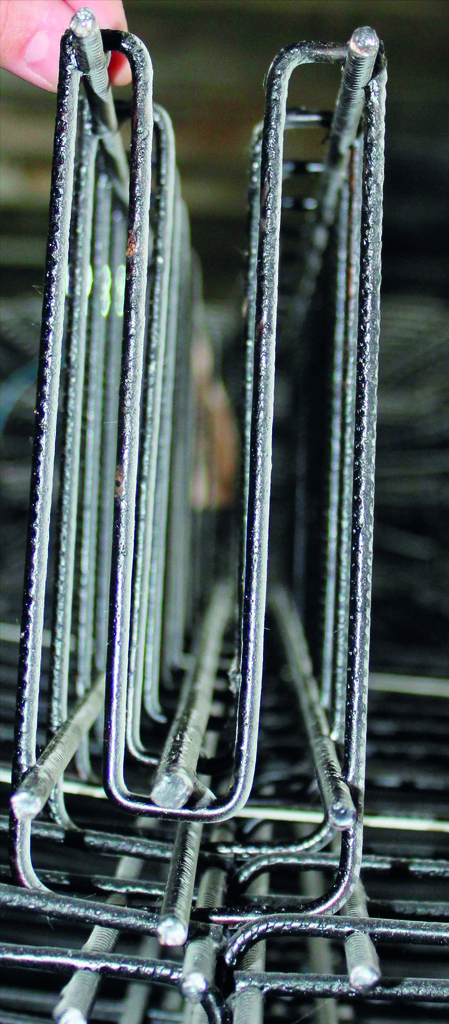
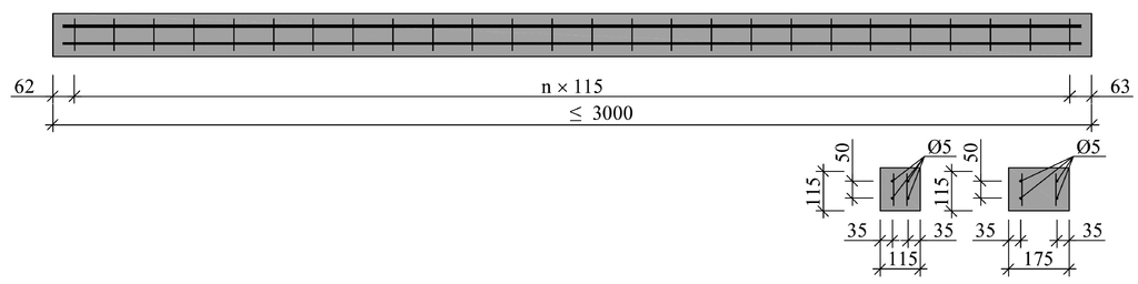
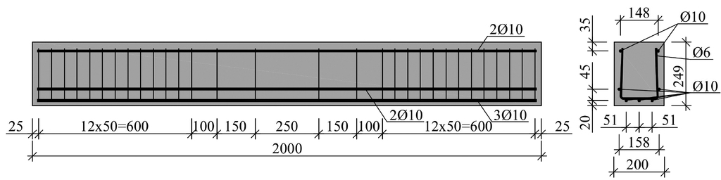
Self-supporting lintels [7] are offered in two fire resistances classes: R30 and R90. They are made of AAC with the density class of 650 kg/m3 and compressive strength of 4 N/mm2. Reinforcement of A-IIIN steel (St3S-b-500) has an anti-corrosion protective coating (water-based paint for metals). Lintels are 24 cm high and 12 or 18 cm wide. The minimum length of support on the masonry is 20 cm for lintels that are 140 or 160 cm long and 25 cm for lintels that are 200 or 230 cm long. The permissible uniform design load is 13.9 to 32.2 kN/m. Fig. 2 shows lintel reinforcement examples and Fig. 3 shows the designs of a composite lintel and self-supporting lintel respectively.
Test conducted at the Silesian University of Technology
Test models and test programme
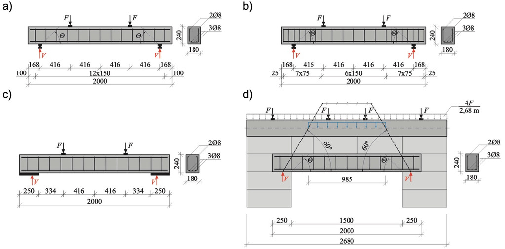
As part of a broad scope of tests on products of AAC conducted at the Faculty of Civil Engineering, Silesian University of Technology, the load capacity of reinforced precast lintels was verified. The first stage of tests included basic tests with lintels tested in compliance with the requirements of PN-EN 1356 [8] as single elements. The second stage included main tests with lintels tested as beams installed in a wall with AAC masonry elements and a ring tie. The tests used two types of lintels with a length of 200 cm, width of 18 cm and height of 24 cm that differed in the spacing of transverse reinforcement. Elements make it possible to overlap openings in structural load-bearing walls with a maximum clear width of no more than 150 cm, with the minimum length of support on masonry a0 = 25 cm. Elements marked with N had stirrups with a fixed spacing of 15 cm along the length of the beam and lintels marked with W had a spacing reduced to 7.5 cm in the zone proximal to the supports.
The basic tests of bending strength of lintels using the four-point bending scheme included three testing series with a minimum of three elements in each series. Series A and G tested N-type lintels while series C tested W-type lintels. Series NIII in the main test stage covered six models of masonry with N-type lintels.
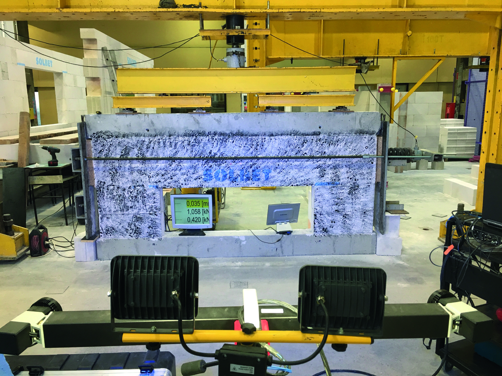
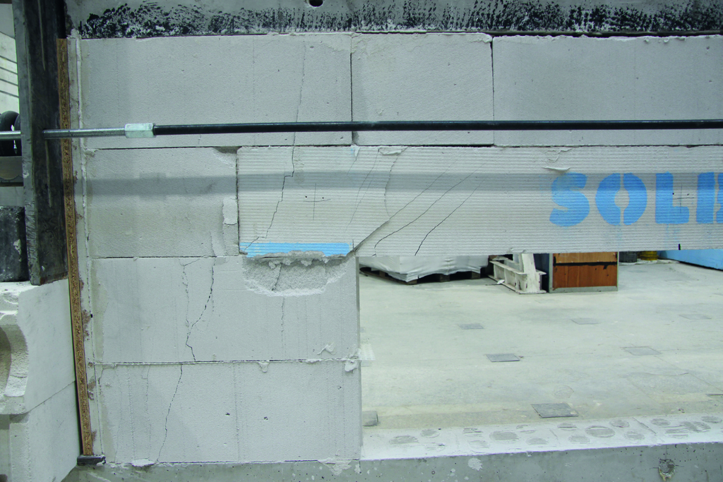
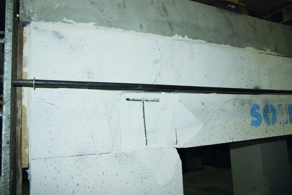
In the second stage, tests were conducted on wall sections representing the upper area of the wall around the window opening (with the clear width of the opening of 150 cm). Lintels were supported on two layers of masonry elements, maintaining the support length of 25 cm and a single layer of masonry elements was laid above the lintel. The masonry was topped with a reinforced concrete beam with a cross-section b×h = 18×22 cm and a length of 268 cm equal to the length of the model. The models were constructed with masonry elements with the dimensions lu×tu×hu = 59×18×24 cm, with tongue and groove, the density class of 600 kg/m3 and standard average compressive strength fb = 4 N/mm2. Thin-layer joint mortar class M5 was used, without filling in head joints. For a view of test models, see Fig. 4 and 5.
In the case of the lintels tested for bending, as the load increased, vertical flexural cracks appeared first in the area between the load application points. As the load increased further, diagonal cracks formed in the section between the load application point and the support. In the final phase of the test, horizontal cracks formed at the height of the bottom reinforcement (Fig. 6a). Based on the morphology of cracking of the beams, the angle of inclination of the decisive destructive crack with respect to the longitudinal axis of the beam was determined. After the tests, the beam reinforcements were inspected visually in the zones proximal to the supports. Buckling of the horizontal stirrup arms was observed in all the lintels (Fig. 6b).
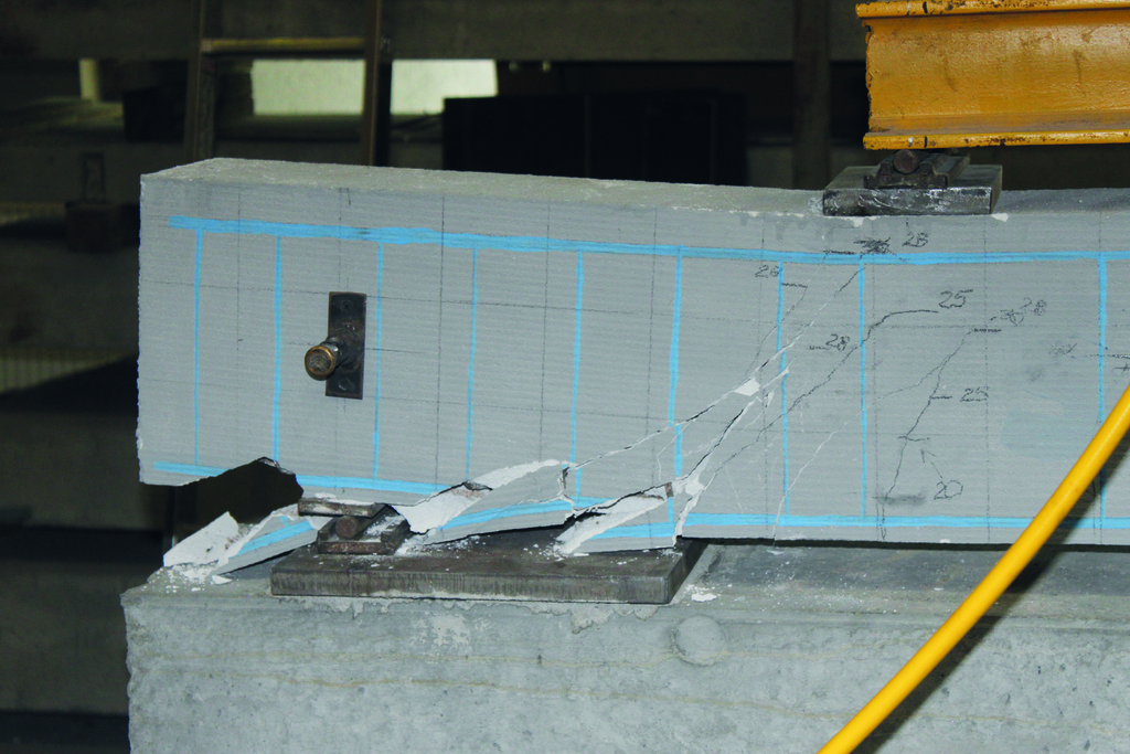
In series NIII covering wall sections, the first cracks to appear were cracks in the bed joints between the masonry elements and the lintel and ring beam, followed by cracks on the lintel. Cracks formed in the lower, middle and upper parts of beams proximal to the supports. This was followed by diagonal cracks forming in the lintels and propagating from the edge of the support and also cracks in the masonry elements supporting the lintels. The test models failed as a result of exhaustion of the compressive capacity of the masonry elements and lintels in the support zone (Fig. 7a). No deformations of the horizontal stirrup arms were observed (Fig. 7b) as was the case in tests series A, C and G.
Test results
Due to the nature of failure of the test models in the support zones, the failure loads were given as force Fi acting via the traverse upon the support and as total load (support response) Vi taking into account the weight of the lintel, steel fixtures, masonry elements and ring beam. In the models in series NIII, the load acting upon the lintel was taken to be the load located in the area within an equilateral triangle (the averaged load acting on ring beam 4F/2.68 m was collected from a length of 985 mm – Fig. 4d). As the predominant type of failure of the elements was shear, the inclination of the compressed concrete cross braces was determined on the basis of the morphology of cracking of the lintels. The results obtained are stated in Table 1.
Table 1: Lintel test results
Series | Element | Fi kN | Fmv kN | Vi kN | Vmv kN |
| ctg(Θtest) | ctg(Θtest)mv |
A | 1 | 10.6 | 12.7 | 11.2 | 13.3 | 0.77 | 0.87 | 0.90 |
2 | 12.5 | 13.1 | 0.93 | |||||
3 | 13.2 | 13.8 | 0.29* | |||||
4 | 14.4 | 15.0 | 0.90 | |||||
C | 1 | 13.9 | 14.1 | 14.5 | 14.7 | 0.85 | 0.87 | 0.91 |
2 | 12.9 | 13.5 | 0.97 | |||||
3 | 15.5 | 16.1 | 0.90 | |||||
G | 1 | 16.4 | 16.7 | 17.0 | 17.3 | 1 | 1.11 | 1.15 |
2 | 19.5 | 20.1 | 0.12* | |||||
3 | 14.2 | 14.8 | 1.19 | |||||
NIII | 1 | 151.2* | 395 | 28.4* | 73.3 | 4.24 | 1.19 | 1.19 |
2 | 357 | 66.3 | 1.33 | |||||
3 | 408 | 75.7 | 0.9* | |||||
4 | 411 | 76.2 | 1.0 | |||||
5 | 365 | 67.8 | 1.19 | |||||
6 | 435 | 80.6 | 1.23 | |||||
* – result ignored in analyses | ||||||||

Safety analysis
The safety analysis of precast AAC elements manufactured in Poland was conducted using the example of reinforced lintels, which were tested as described above. Attempts were made to verify qualitatively and quantitatively the rules for determining the valid effect of combinations of external impacts compliant with PN-EN 1990 [9]. A sustainable design situation was considered, and it was verified whether the shear safety condition ULS defined as the equality of the design effect of impact Ed resulting from the most disadvantageous combination of all loads and the effect of random load capacity Rd ensured an acceptable safety level. The proposed method assumed that the global reliability index β was an objective measure of the safety level and the design values of impacts determined in each combination and the design load capacities of the cross-section proximal to the supports were calibrated using partial safety factors established in the standard [9]. Finally, the characteristic fixed loads of floors with flooring layers providing the required level of lintel shear safety were determined and related to the characteristic fixed loads of floors manufactured in Poland.
A detailed safety analysis can be found in [3]. For a list of floor parameters taken for calculations, see Table 2. The results of lintel test series A, C, G and NIII discussed in detail in the above section were considered.
Table 2: List of technical parameters of floors taken for the lintel analysis
No. | floor type | floor model | dead load of floor, kN/m2 | recommended useful load of floor, kN/m2 | fixed load of floor with flooring layers, gks kN/m2 |
| ||||||
rule 'a' equation 6.10 [9] | rule 'b' equations 6.10a and 6.10b [9] | |||||||||||
min. | max. | min. | max. | min. | max. | min. | max. | min. | max. | |||
1 | rib-and-slab floors | monolithic floors filled with ceramic and concrete blocks | 2.35 | 3.60 | 1.5 | 3.25 | 3.65 | 0,00 | 0.20 | 0.33 | 0.20 | 0.32 |
2 | floors filled with blocks made of materials other than ceramic | 2.0 | 3.25 | 2.0 | 3.30 | 5.65 | 0.18 | 0.31 | 0.18 | 0.30 | ||
3 | prefabricated monolithic floors on reinforced concrete or ceramic and reinforced concrete beams | 2.8 | 3.75 | 4.5 | 4.10 | 6.15 | 0.23 | 0.34 | 0.22 | 0.33 | ||
4 | prefabricated monolithic floors on trussed beams with ceramic and reinforced concrete or reinforced concrete flanges | 2.0 | 5.0 | 1.5 | 7.0 | 3.30 | 7.40 | 0.18 | 0.41 | 0.18 | 0.40 | |
5 | prefabricated monolithic floors on prestressed beams | 1.72 | 4.6 | 1.5 | 2.0 | 3.02 | 7.00 | 0.17 | 0.39 | 0.16 | 0.37 | |
6 | slab floors | with unidirectional reinforcement | 2.0 | 4.0 | -- | 3.30 | 6.40 | 0.18 | 0.35 | 0.18 | 0.34 | |
7 | with cross reinforcement | 2.0 | 5.0 | -- | 3.30 | 7.40 | 0.18 | 0.41 | 0.18 | 0.40 | ||
8 | filigree composite slab floors | 4.0 | 5.0 | -- | 5.30 | 7.40 | 0.29 | 0.41 | 0.28 | 0.40 | ||
9 | panel floors | 2.5 | 6.0 | -- | 3.80 | 8.40 | 0.21 | 0.46 | 0.20 | 0.45 | ||
10 | prefabricated slab floors | 2.5 | 3.47 | 1.28 | 6.78 | 3.80 | 5.87 | 0.21 | 0.32 | 0.20 | 0.31 | |
11 | AAC slab floors | 1.03 | 2.06 | 4.25 | 5.0 | 2.33 | 5.00 | 0.13 | 0.28 | 0.12 | 0.27 | |
min./max. | 2.33 | 8.40 | 0.13 | 0.46 | 0.12 | 0.45 | ||||||
Analysis results
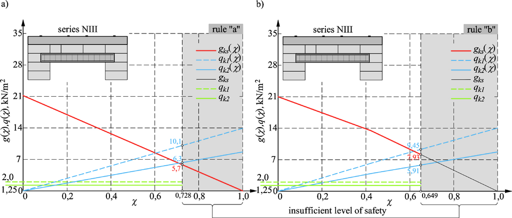
At this stage of the analysis, only lintels of series NIII, which were the most similar to the actual design case, were considered. For a comparison of the obtained results of calculations, allowing for combination rules 'a' – equation 6.10 [9] and 'b' – equations 6.10a and 6.10b [9], see Fig. 8. The comparison shows that for typical changing loads on floors with an axial span of 6 m, the proportions of actual fixed loads and fixed loads calculated according to the proposed procedure reach a maximum of 46% in both load rules used. The calculation analysis based on the results of lab tests and the tradition of determining internal forces in the lintels and the floor solutions used in Poland indicate sufficient safety levels when the lintels are properly supported. A factor that reduces the safety level of the structure is the increase in the proportion of the changing loads on the floors in relation to the total loads (increase in the factor χ – the ratio of characteristic dead loads and the total dead and variable loads).
Summary
The analyses carried out have shown that it is safe to use reinforced AAC lintels that are currently manufactured. However, one cannot rule out construction errors, e.g. reverse installation of elements. Such defects should be eliminated during the acceptance phase of the works. In existing structures mainly of roof slabs and floors, damage can occur as a result of overloads or corrosion of reinforcement due to moisture or manufacturing errors.
Standard tests of lintels have shown the importance of the influence of the support of the elements on their load-bearing capacity in the support zone. In elements (series G) where pressure was applied across the entire support zone, an increase in the total load of 30% was achieved. The tests of the lintels together with masonry sections and the reinforced concrete ring beam confirmed the cooperation of all elements of the models giving a several-fold increase in the total load (73.3/17.3 = 4.24). In the design phase, by compiling the reduced load on the lintel using the "equilateral triangle" method, it is possible to obtain a load many times greater than the load capacity of the lintel alone without taking into account the load capacity of the entire lintel-masonry-ring beam arrangement. As a result, a reinforced concrete or steel lintel will be used instead of the AAC lintel, which is convenient to install and safe to use.
One arrives at a clear conclusion that by designing the lintels according to the standard rules and the traditional approach for determining the design internal forces in the lintels, and provided the elements rest adequately on the supports, an adequate level of safety of the structure is ensured. An insufficient load-bearing capacity and the occurrence of a failure condition most often result from construction and operational errors.
References
[1] Goodier Ch., Cavalaro S., Gorse Ch., Blay K., Blanco-Alvarez A.: Structural performance of aged Reinforced Autoclaved Aerated Concrete (RAAC) roof panels. CE/Papers, vol. 6, issue 2, p. 134.
[2] https://www.bbc.com/news/education-66669239 (accessed on 11.05.2024).
[3] Drobiec Ł., Jasiński R., Mazur W.: Safety of reinforced AAC structures. Cement, Wapno, Beton 29(2) 108-131 (2024), doi:10.32047/CWB.2024.29.2.3.
[4] Ytong product catalogue.
[5] Termalica product catalogue.
[6] H+H product catalogue.
[7] SOLBET product catalogue.
[8] PN-EN 1356:1999 Performance test for prefabricated reinforced components of autoclaved aerated concrete or lightweight aggregate concrete with open structure under transverse load.
[9] PN-EN 1990:2004 Fundamentals of structural design.