Application & Construction
Experimental Shaking Table Study
Seismic Performance of Lightweight and Sustainable AAC Constructions
Loading...
Christoph Butenweg is Professor at the FH Aachen University of Applied Sciences, Visiting Professor at the University of Belgrade, Visiting Lecturer at RWTH Aachen University and Business Manager and Associate of the engineering company SDA-engineering GmbH. He is chairman of the code committees NA 005-51-06 and NA 005-06-37 AA and member of the Executive Boards of the European Association of Earthquake Engineering the Center for Wind and Earthquake Engineering (CWE) at RWTH Aachen University.

Dietlinde Köber is Associate Professor at the Technical University Bucharest, Romania and Visiting Professor at Hochschule für Technik, Wirtschaft und Gestaltung Konstanz, Germany. She is an active design and verifying engineer for concrete, masonry and timber civil structures. She is a member of Work Group 8 on Irregular and Complex Structures and of Work Group 12 on Continuing Education and Professional Development of the European Association of Earthquake Engineering. She is also a member of the author team for the Romanian Seismic Codes for new (P100-1) and existing structures (P100-3).

Lorenzo Miccoli is Project Leader at the Xella Technologie-und Forschungsgesellschaft mbH. He was a Research Associate at the Bundesanstalt für Materialforschung und – prüfung (BAM) from 2011 to 2017. He received his PhD in Building Engineering at the University of Rome ‘Tor Vergata’. He was a visiting researcher at the University of South Carolina in 2016 and at the Yangzhou University in 2005. He is member of the technical committee of the European Autoclaved Aerated Concrete Association (EAACA). He is a member of the CEN TC 250/SC6.PT2 for the revision of the Eurocode EN 1996-1-2 and of the code committees NA 005-51-06 and NA 005-06-37 AA. His main research focuses on mechanical characterization of masonry, finite element modelling, seismic and fire resistance, dynamic and static analysis of buildings.

Markus Heße is Head of International Product Management with Xella Baustoffe GmbH. After studying civil engineering at Aachen University and construction management at the University of Birmingham in UK with distinctions for outstanding results, Markus Heße has been working for the current Xella building materials group for over 25 years. Positions in sales, key account management, research and development, and product management at Xella Deutschland characterize his career. Tasks related to the support of countries and the development of new application solutions with high-performance building materials are the main features of his daily work. The technical support of license partners around the world is another part of the work. As a speaker at national and international events, he reports on developments and progress in the area of products and digital solutions for the Xella Building Materials Group. On a European level, he is involved in the task group “Digitalization” at the European building materials association.
Unreinforced masonry has long been prevalent in European housing thanks to its simplicity, durability and thermal efficiency. However, its seismic vulnerability has been repeatedly demonstrated in earthquakes in Turkey and Italy. The updated European Seismic Hazard Model ESHM 2020 [2] highlights that this weakness also affects regions of moderate seismicity, where traditional masonry frequently fails to meet safety standards. Consequently, masonry is increasingly being replaced by reinforced concrete, despite the higher costs and environmental impact of the latter. Against this backdrop, the ECORE project was launched to evaluate the seismic performance of a new innovative lightweight construction system with AAC walls through shaking-table tests. The aim of this system is to reduce seismic forces by lowering structural mass with lightweight concrete slabs and beams and autoclaved aerated concrete (AAC) walls, while minimising CO₂ emissions using low-carbon concrete. Seismic resistance is further enhanced by using AAC formwork blocks that incorporate reinforced concrete (RC) columns, as well as the innovative recycled-material connection INODIS-P for partition walls. The system's modular design and straightforward assembly also allow for rapid and efficient on-site construction. The ECORE consortium comprises a multidisciplinary network of universities, research institutes and industrial partners from Germany, Greece, Romania and Switzerland. The Technical University of Civil Engineering in Bucharest coordinated the experimental programme, which was conducted on the AZALEE shaking table at CEA Paris-Saclay.
Description of the test structure system
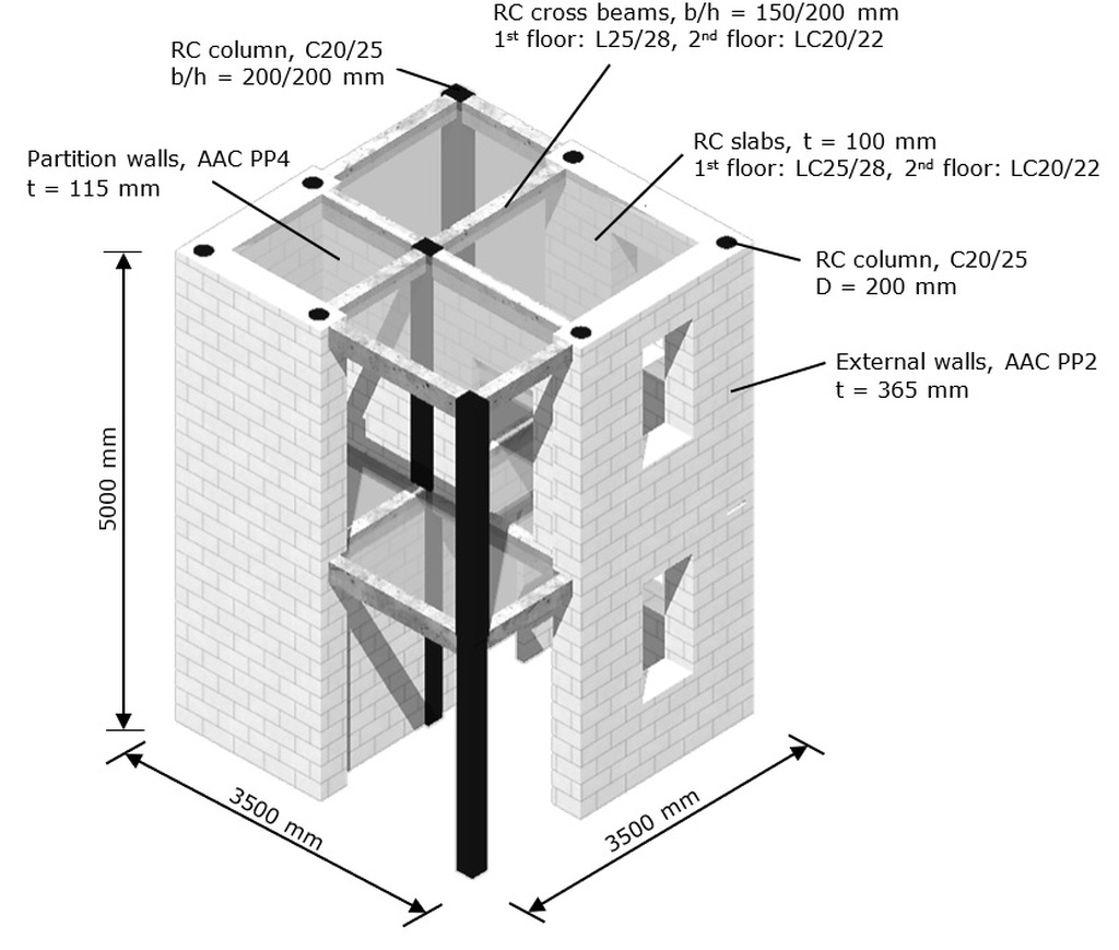
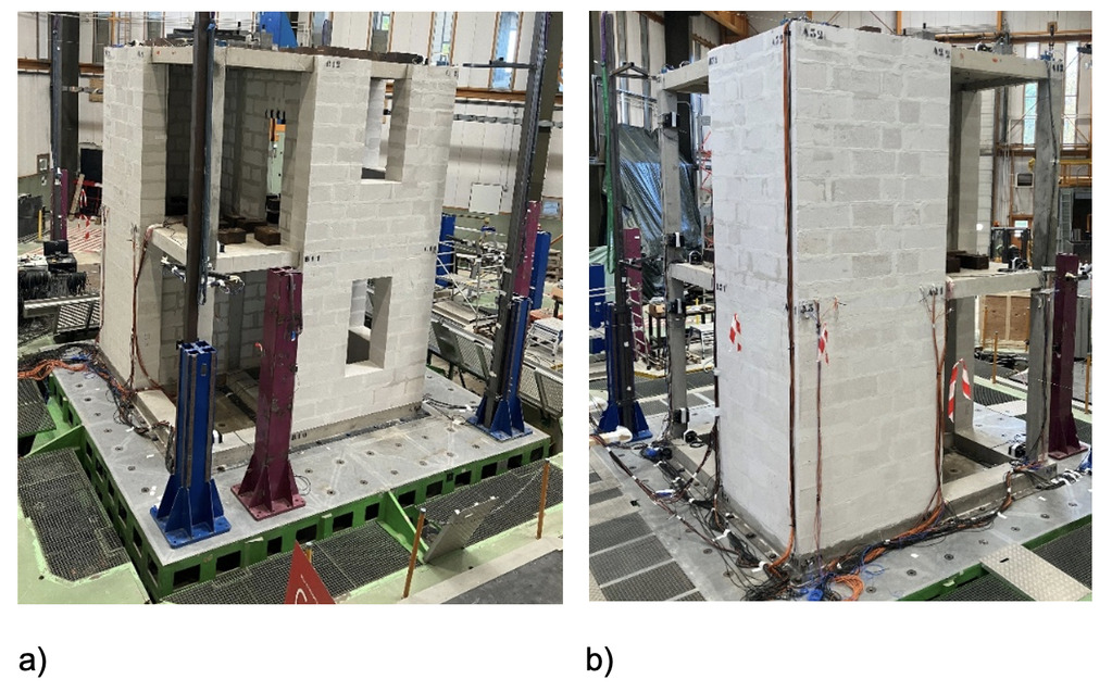
The model of the two-storey test structure, with materials and dimensions shown in Figure 1, employs a lightweight frame system consisting of reinforced concrete (RC) columns, beams, and slabs, complemented by highly thermally insulating AAC exterior walls. Within the structure, non-loadbearing AAC partition walls with openings are positioned perpendicular (rotated 90°) to the exterior axes. The building has a square footprint of about 3.5 × 3.5 m, with a story height of 2.5 m. It rests on a grid of RC beams, enabling both transport and secure anchoring to the shaking table using anchor rods. The cross beams and the slabs are constructed from lightweight concrete LC 25/28 at ground floor level and LC 20/22 at first floor level. The columns, made of normal-weight concrete C20/25, were cast in two configurations: circular with a 200 mm diameter when integrated into AAC form blocks at the corners, and square when cast conventionally. The AAC masonry employs Ytong PP2-0,35 for the exterior walls and Ytong ThermCombi PP4-0,55 for the interior partitions executed in combination with thin-bed layer mortar Ytong FIX N240 [6]. Fig. 2 shows the front and back view of the test structure on the shaking table.
Construction of the test structure
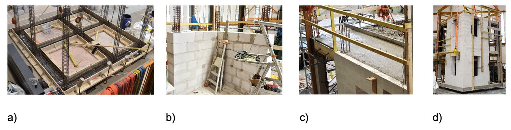
The test structure was constructed on a grid of reinforced concrete beams, cast onto 10 mm thick steel plates with headed studs to ensure a rigid connection to the shaking table through plate anchorage. The beam dimensions are 365/200 mm at the perimeter and 300/200 mm in the interior. Fig. 3a shows the formwork, the reinforcement of the foundation beams and the upward extension of the column reinforcement. In the next step, the exterior walls of the ground floor were constructed with AAC blocks, using formwork blocks with 200 mm circular openings at the wall ends, laid in staggered layers. The blocks were concreted in sections with adequate compaction during wall erection. The final concreting of the column - beam joints was executed together with the floor slab above, employing LC on both stories. On the ground floor, window openings were equipped with lintels to support the AAC masonry above, whereas on the upper floor the openings extend to the level of the reinforced concrete beam, thereby dispensing with the need for lintels. Fig. 3b illustrates the placement of formwork blocks, and Fig. 3c the casting of the slab on the first floor. After completion of both stories, the test structure constructed in the hall area was transported onto the shaking table by crane. For this purpose, steel profiles were installed below the first-floor slab through openings in the exterior walls, to which the entire structure was attached. In addition, the walls were braced with wooden battens. Since the maximum crane capacity was limited to 25 t, the relocation was carried out before the installation of the partition walls. Fig. 3d shows the structure during the lifting process.
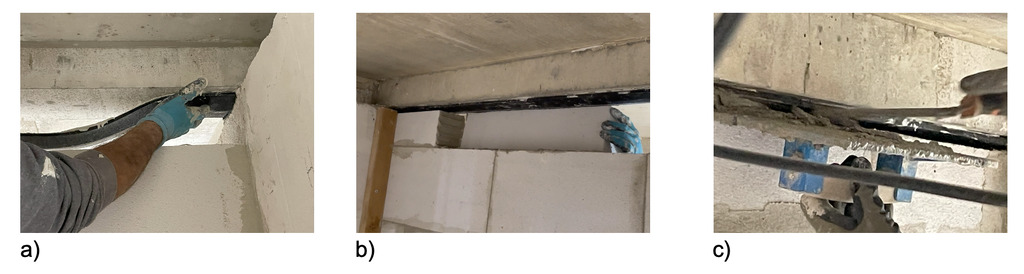
In the last step the partition walls were installed in perpendicular direction on the ground and first floor (Fig. 1). The larger span includes a door opening, whereas the smaller span remains solid without any openings. Partition walls were installed together with the INODIS-P connection profile [1] to ensure complete grouting of the joint, which is essential for developing the arching action required to safely transfer inertia forces acting perpendicular to the partition walls. A strong bond between the concrete and the profile is achieved by applying a fleece coating to the flat side of the profile, used in combination with thin-bed mortar. Thanks to its triangular shape, the grouting process was easily carried out. Fig. 4 shows the installation process: (a) attaching the INODIS-P profile [1] to the slab with thin-bed mortar, (b) inserting the final brick course, and (c) filling the remaining gap with mortar.
Seismic action
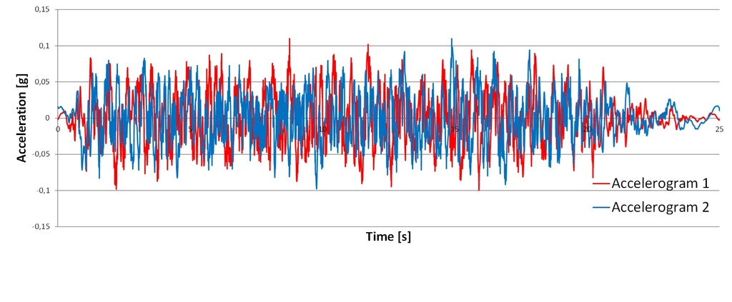
The seismic action is defined by a linear elastic response spectrum of Type 1 with soil condition C, in accordance with Eurocode 8 [4]. Two stochastically independent accelerograms, baseline-corrected and compatible with this spectrum, were generated with a total duration of 25 s. The test structure was subjected to bidirectional seismic input using the two accelerograms scaled to identical levels of Peak Ground Acceleration (PGA). As an example, Fig. 3 shows the artificial accelerograms scaled to a PGA value of 0.1g.
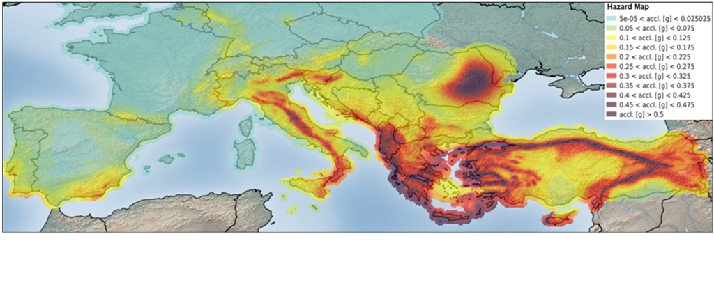
During the test campaign the accelerograms were scaled up to a maximum of 0.9g. To put this value into context, Fig. 6 shows the seismic hazard map for Europe based on PGA values from the 2020 European Seismic Hazard Model (ESHM20)[3]. The model provides updated, harmonized probabilistic maps of ground-shaking levels for a return period of 475 years. These maps are also part of the second generation of Eurocode 8 [4] and the first pan-European earthquake risk model. The comparison shows that the PGA values reached in the prototype structure are very high and far exceed those indicated in the hazard map.
Experimental results
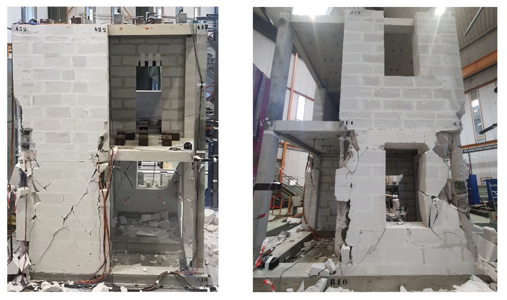
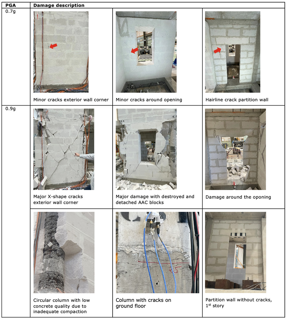
The shaking table test was carried out for PGA levels of 0.1g, 0.19g, 0.35g, 0.5g, 0.7g, and 0.9g. After the application of each load level, a visual inspection of the damage patterns in the RC components and AAC walls was performed. It was observed that the structure exhibited linear elastic behaviour up to a load level of 0.35g. Only hairline cracks appeared around the openings in the exterior and partition AAC walls at the ground floor, while beams and columns remained free of cracks. Crack formation in RC columns started at load levels of 0.5g and 0.7g, with fine horizontal cracks mainly observed at the beam–column connection. Furthermore, cracks were detected in the AAC walls in the connection areas to the embedded columns and around openings. Overall, the structure showed robust behaviour and stable interaction between the RC frame and the AAC walls up to 0.7g. At a load level of 0.9g, plastic hinges developed in RC circular columns of the ground floor with visible crack formation (Fig. 8), which subsequently led to large deformations and load redistribution onto the masonry walls. The first story exhibited nearly linear behaviour, acting as a rigid body on the flexible ground floor, with no significant structural damage observed. Fig. 7 shows the damage to the test structure after applying a load level of 0.9g, and Fig. 8 shows the observed damage in selected components at load levels of 0.7g and 0.9g.
The observed behaviour is confirmed by the measured drift values, which ranged from 0.3% to 0.43% in the ground floor and 0.05% in the upper floor. Plastic hinges formed in the columns, although according to capacity design they should have developed in the beams. Further examination of the test structure revealed that the circular columns suffered from inadequate concrete compaction (Fig. 8). Nevertheless, very high acceleration values were attained, as the use of lightweight materials reduced the resulting inertial forces. The findings emphasize that adequate compaction and proper aggregate grading of the concrete in the integrated circular columns are critical factors for structural performance. It is also interesting to note that the partition walls on the first floor showed no damage, even though the story accelerations up to the formation of plastic hinges on the ground floor reached values of 20 and 30 m/s² in both directions. This demonstrates that a stable compression arch developed within the thin partitions with INODIS-P [1].
Summary
The test results demonstrate the great potential of lightweight structural systems with AAC walls in seismic regions. The maximum peak ground acceleration (PGA) achieved in the tests, 0.9g, were significantly higher than the PGA acceleration levels expected in Europe according to the new European seismic hazard maps [2],[3]. The experiments further showed that careful execution of the embedded reinforced concrete columns in the hollow blocks is of essential importance for seismic performance. To make the findings available for practical application, a feasible design and verification concept needs to be developed and implemented. A linear calculation model for capturing the interaction of integrated columns in AAC walls has already been developed by Xella T&F and is already available in a design software tool for practice [5]. Nevertheless, further development and research are needed to make the reserves even more accessible in practice.
Acknowledgement
This work is part of the transnational access project "ERIES-ECORE", supported by the Engineering Research Infrastructures for European Synergies (ERIES) project (www.eries.eu), which has received funding from the European Union's Horizon Europe Framework Programme under Grant Agreement No. 101058684. This is ERIES publication number J14.
References
[1] Butenweg, C., Kubalski, Th., Miccoli, L., Heße, M.: Integrated RC columns in formwork blocks and new partition wall connection, AAC Worldwide, issue 3, 2025.
[2] Danciu, L., Giardini, D., Weatherill, G., Basili, R., Nandan, S. , Rovida, A., Beauval, C. , Bard, P-Y., Pagani, M., Reyes, C.G., Sesetyan, K., Vilanova, S., Cotton, F., Wiemer, S.: The 2020 European Seismic Hazard Model: overview and results, NHESS, 24, 3049–3073, 2024, https://doi.org/10.5194/nhess-24-3049-2024.
[3] EFEHR: https://hazard.efehr.org/en/hazard-data-access/hazard-maps/
[4] Eurocode 8: Design of structures for earthquake resistance – Part 1: General rules, seismic actions and rules for buildings, European Committee for Standardization, 2004.
[5] MINEA: Analysis and design of masonry structures, SDA-Solutions GmbH, Herzogenrath, www.minea-design.com, 2025.
[6] Xella Technologie- und Forschungsgesellschaft mbH, Testing of material properties of AAC blocks Ytong PP2-0,35, Ytong ThermCombi PP4-0,55 and thin layer mortar Ytong FIX N240, 2023