Production Technology
Reducing energy consumption
Thermal use of exhaust steam in the AAC production process
Loading...
Martin Schopflocher (born 1961) obtained his degree in mechanical engineering at the Buenos Aires University in 1992. He has been working in the AAC industry for the last 24 years focusing on different technical areas: optimization of production processes, quality control procedures for AAC products, and research in AAC plant design worldwide. He is now the CTO of retak, the leading producer of AAC products in Argentina. martins@retak.com.ar
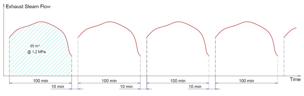
One of the crucial processes in the production of AAC is the correct control of pressure gradients during loading and discharging steam to and from autoclaves. Discharge of spent steam, which is located inside autoclaves once the pressure maintenance has been completed, is normally carried out automatically through a control valve until atmospheric pressure is reached. This autoclave discharge process is repeated sequentially throughout 24 hours/day. The availability of exhausted steam from autoclaves, which was originally discharged directly to the atmosphere, varies over the production process (Fig. 1). This must be accounted for in order to avoid any delays in the autoclaving process.
Even when exhausted steam is transferred to another autoclave, just after completion of the vacuum stage, a significant amount of steam must be released with the consequent loss of thermal energy contained in this vented exhaust steam. The reason is that the steam transfer among autoclaves is possible only up to the point when the flow becomes so slow that the set discharge gradient can no longer be maintained.
Key facts – main achieved results
· Natural gas saving: 9.7%
· Reduction of CO2 emission: 301.6 tons/year
· Inversion amortization period: less than 20 months
Objectives and proposed solutions
The main objective of the optimization was to achieve a recovery of the thermal energy contained in the exhausted steam vented in each autoclave cycle (12 times per day). The Argentinian company Flowproen S.R.L., dedicated to design and optimization of chemical and thermal equipment for industrial processes, was contracted to assist Ardal S.A. in developing a technical solution that would allow optimum thermal harnessing of the exhausted autoclave steam in order to preheat the feed water from the steam boiler of the plant. Originally, the preheating of the boiler feed water was carried out by direct injection of life steam into the feed tank, heating the water up to 55°C. This process was related to extra consumption of steam from the boiler. The idea was to replace this system and achieve higher water preheating temperatures using as a heat source the latent energy contained in the condensed exhausted steam from autoclaves.
Technical boundary conditions for the process
The following boundary conditions had to be taken into account:
1) Flow and pressure conditions of the exhausted steam are highly variable over time.
2) The process of discharging the exhausted steam from autoclaves must not result in an alteration of the preset pressure curve, as this would result in delays in the autoclave curing cycles.
3) The exhausted steam is inevitably contaminated with various impurities: AAC particles, oil drops, iron rust, air and humidity.
4) The water demand of the boiler is variable over time.
5) The supply of feed water for the boiler must be reliable; a minimum and maximum level in the preheated water tank must be guaranteed.
6) The heat recovery station to be implemented must be completely automatic, not requiring the attention of operators for its normal operation.
7) The system must achieve optimum performance by obtaining the maximum condensation of the exhausted steam in the heat exchanger of the system.
Principal components
The following principal components were developed to address the above boundary conditions:
a) A water circulation pump with variable frequency to control the flow in the secondary circuit of the heat exchanger. This control of the water flow is necessary to compensate the variable conditions of flow and the steam pressure in the primary circuit. In this way, the condensation of all the steam exhausted from the autoclaves is completed without altering the pressure gradient imposed by the autoclave process. This solves the challenges associated with Conditions 1) and 2) above.
b) A special heat exchanger that admits circulation of steam with a certain degree of contamination and allows simple periodic disassembly for inspection and cleaning of accumulated dirt. This addresses Condition 3)
c) A three-way control valve that allows to permanently change the flow rates of water between tanks or recirculate water through the heat exchanger, harvesting the maximum available heat at any time. This addresses Condition 4)
d) Level sensors in the water storage tank for feeding the boiler allow efficient control of flow rates, ensuring safe water levels inside the tank. This addresses Condition 5)
e) Pressure and temperature transmitters and self-piloted safety valves in fluid circuits that constantly monitor optimal operating conditions and guarantee the autonomous and safe operation of the system. This addresses Condition 6)
f) The correct dimensioning of the heat exchanger. The variable flow of water in the secondary circuit added to an efficient steam trap at the outlet of the exchanger, where the condensate is constantly removed. In this manner, internal waterlogging (stall effect) is avoided and the transfer of heat to the boiler feed water is maximized. This addresses Condition 7)
Development of the solution
First stage: measurements
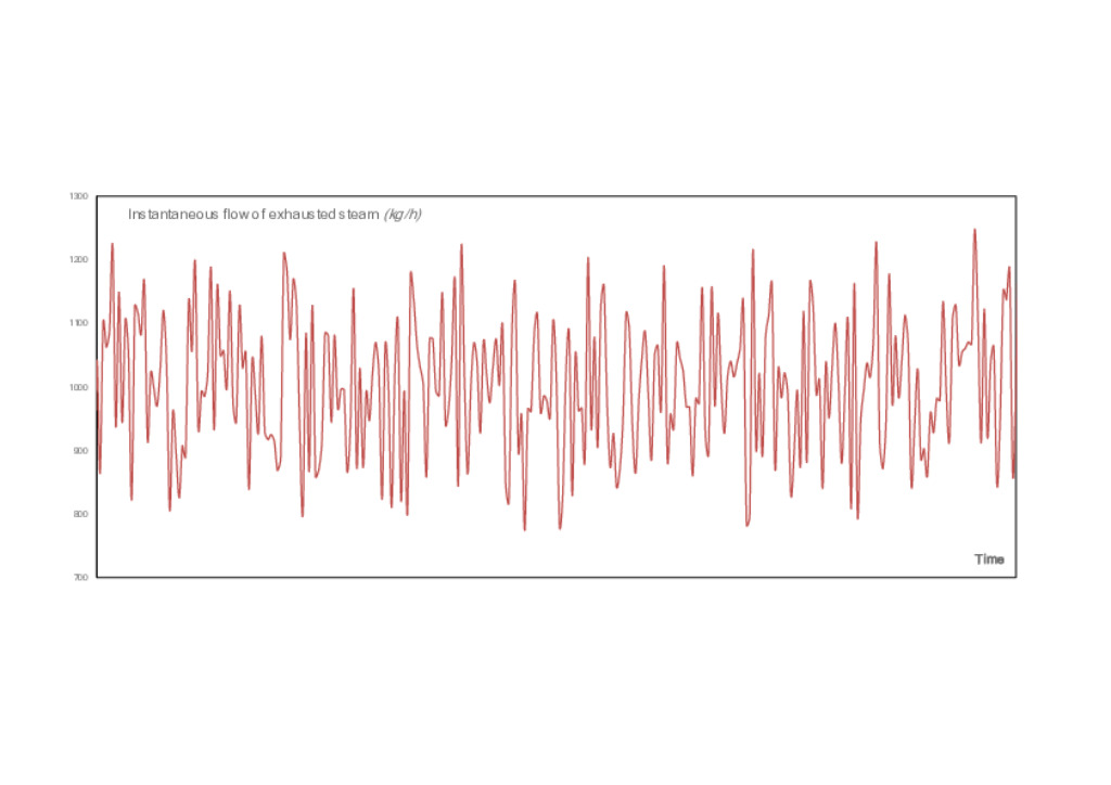
During a plant survey, flowmeters were temporarily installed in steam lines in order to accurately measure the flow rates of the inlet and outlet steam from autoclaves and thus estimate the flow of exhausted steam vented to the atmosphere, aiming at making it available for feeding the new energy recovery station. The instantaneous flow rate of exhausted steam from autoclaves registered fluctuations throughout a normal production period, as shown in Fig. 2. The variability of pressure and flow rate of this steam necessitated equipping the heat recovery system with a certain “intelligence”, which was done by adding some peripheries around the heat exchanger in order to respond optimally to all external conditions.
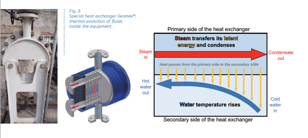
Second stage: heat exchanger design solution
A hybrid shell and plate heat exchanger from the German company Gesmex® was selected for its robustness and compact design, which allows easy disassembly for internal cleaning (Fig. 3).
The motor of the water circulation pump will increase its speed progressively when: i) the sensed steam pressure rises at the inlet of the heat exchanger, ii) the sensed water temperature increases at the outlet of the exchanger and iii) the water level inside the feed water tank drops; and vice versa.
The three-way control valve will modulate its position, dosing higher recirculation flow rates and reducing the addition of make-up water as the water level within the feed tank approaches its maximum; and vice versa.
Variable operating bands were established so that the reaction of the different actuators of the system presents a stable and safe integral behavior.
The measurement elements that were required include pressure sensor (PT), pressure gauge (PI), temperature sensor (TT), temperature indicator (TI) and flow sensor (QT). The active components that were used include: three-way control valve, automatic ON/OFF valve, a pressure safety valve, a steam trap, the water circulation pump (with variable speed drive) and the PLC for functional control with an HMI for the configuration of the control and security system (Fig. 4).
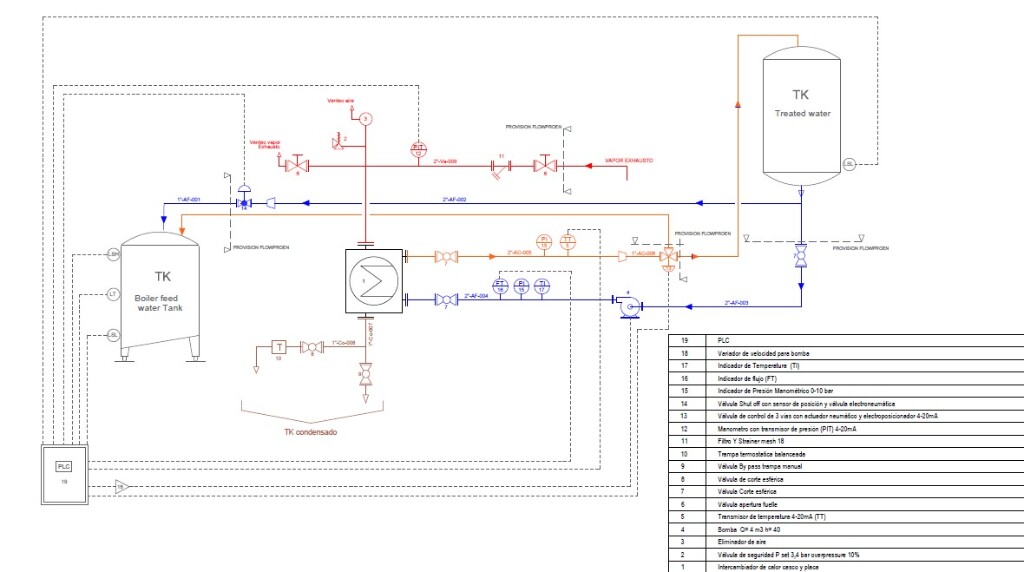
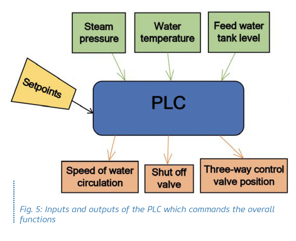
The input signals to the PLC include the levels of the feed water tanks through an analog transmitter (4-20 mA), the water temperature at the heat exchanger outlet (4-20 mA), the steam pressure at the heat exchanger inlet (4-20 mA), the water flow (digital signal) and the maximum and minimum levels (digital signal). The PLC commanded variables include the speed of the water circulation pump, which feeds the exchanger, through a frequency inverter (primary control loop), the position of the three-way control valve pneumatically operated for the control of recirculation flow rates from the water to the treated water tank or circulation to the feed water tank (secondary control loop) and finally the shut off valve for direct water supply bypassing the heat exchanger (Fig. 5).
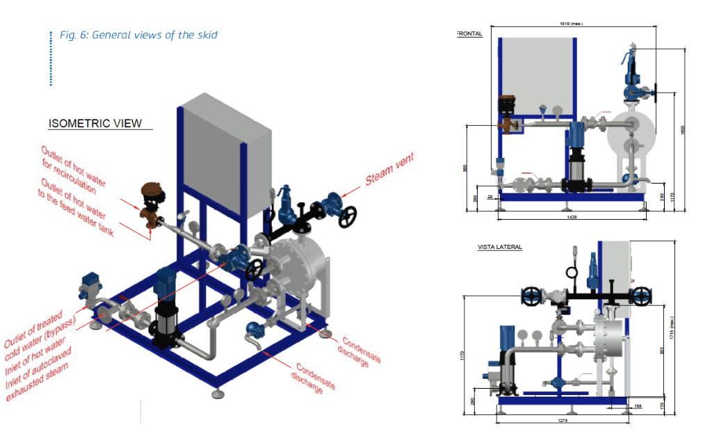
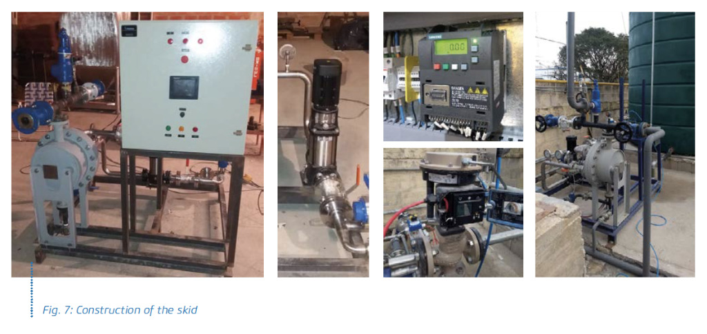
Skid design
A compact skid-mounted system was designed with separate easy-to-install steam and water connections (Figs. 6, 7).
Conclusions
After adjusting and tuning the operating logic, finding the optimal settings, and ensuring that the installation reaches a stable operating regime, an average temperature inside the boiler feed water tank of 87°C was obtained (without any need for external heating by injection of live steam).
After a year of continuous operation, a saving of 9,7% was recorded in the consumption of natural gas in the boiler burner, due to the increase in the temperature of the feed water. This confirms the well known thermodinamic rule: for every 6°C of increase in the feed water temperature, 1% fewer combustion energy is needed in the boiler. Apart from this relevant economic benefit, other additional goals that were achieved with the implementation of the heat recovery system included the following:
• The boiler performance is improved by eliminating the thermal shocks associated with each entrance of low-temperature water.
• It was possible to eliminate the visible exhausted vapor plume that was produced in the vent to the atmosphere.
• Currently, all the produced condensed steam is incorporated in the manufacturing process (sand milling and return slurry pit), which reduces the consumption of drinking water in the plant.
• A reduction in CO2 emission was achieved due to the lower amount of natural gas combustion required in the boiler burner.
• The system reduces required addition of chemical sequestrants of oxygen contained in the boiler water, since the solubility of O2 in the water strongly decreases as its temperature rises.
The period of simple amortization (payback) of the total required investment involved in the execution of this project was less than 20 months.
References
- Steam and Condensate Loop - Spirax Sarco®.
- Energy Assessment Efficiency Book - Bureau of Energy Efficiency.
- Gesmex® and Flowproen® Product Specifications.