Science & Innovation
Innovative approaches for earthquake-resistant constructions with AAC
Integrated RC columns in formwork blocks and new partition wall connection
Loading...Christoph Butenweg is Professor at the FH Aachen University of Applied Sciences, Visiting Professor at the University of Belgrade, Visiting Lecturer at RWTH Aachen University and Business Manager and Associate of the engineering company SDA-engineering GmbH. He is chairman of the code committees NA 005-51-06 and NA 005-06-37 AA and member of the Executive Boards of the European Association of Earthquake Engineering the Center for Wind and Earthquake Engineering (CWE) at RWTH Aachen University.

Thomas Kubalski is Project Engineer at SDA-engineering GmbH. He received his PhD from RWTH Aachen University where he used to work as Research Assistant at the Chair of Structural Analysis and Dynamics from 2013 to 2019.

Lorenzo Miccoli is Project Leader at the Xella Technologie-und Forschungsgesellschaft mbH. He was a Research Associate at the Bundesanstalt für Materialforschung und – prüfung (BAM) from 2011 to 2017. He received his PhD in Building Engineering at the University of Rome ‘Tor Vergata’. He was a visiting researcher at the University of South Carolina in 2016 and at the Yangzhou University in 2005. He is member of the technical committee of the European Autoclaved Aerated Concrete Association (EAACA). He is a member of the CEN TC 250/SC6.PT2 for the revision of the Eurocode EN 1996-1-2 and of the code committees NA 005-51-06 and NA 005-06-37 AA. His main research focuses on mechanical characterization of masonry, finite element modelling, seismic and fire resistance, dynamic and static analysis of buildings.
Markus Heße is Head of International Product Management with Xella Baustoffe GmbH. After studying civil engineering at Aachen University and construction management at the University of Birmingham in UK with distinctions for outstanding results, Markus Heße has been working for the current Xella building materials group for over 25 years. Positions in sales, key account management, research and development, and product management at Xella Deutschland characterize his career. Tasks related to the support of countries and the development of new application solutions with high-performance building materials are the main features of his daily work. The technical support of license partners around the world is another part of the work. As a speaker at national and international events, he reports on developments and progress in the area of products and digital solutions for the Xella Building Materials Group. On a European level, he is involved in the task group "Digitalization" at the European building materials association.
Introduction
In recent years, there has been a significant increase in demand for modern multi-storey buildings made of autoclaved aerated concrete for economic, spatial, social and urban planning reasons. The construction method of a typical multi-storey building, as shown in Figure 1, requires high levels of structural resistance, fire protection and sound insulation, which must be provided by both load-bearing and non-load-bearing partition walls.
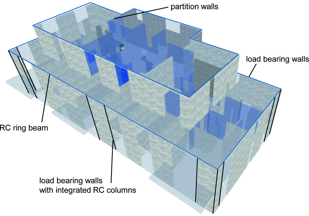
Integral solutions are available to meet structural requirements in earthquake-prone areas and improve the seismic performance of load-bearing structures and non-load-bearing walls made of AAC. One effective approach to increase the earthquake resistance of load-bearing structures consisting of shear walls and load-distributing floors with ring beams is to enhance the load-bearing and deformation capacity of the structural walls using integrated reinforced concrete columns. These columns are cast into AAC formwork blocks at the ends of the walls. The targeted and regular arrangement of these additional tension and compression columns in the floor plan increases the load-bearing capacity of the individual walls and achieves greater compactness through the box behaviour of the overall building. Consequently, the seismic resistance of the entire structure can be significantly enhanced without altering the conventional masonry construction process.
The increased damage to non-load-bearing partition walls perpendicular to their plane that occurred during the recent earthquakes in Italy and Türkiye can be avoided by a rigid connection to the floor slabs. The implementation and design principles of the two solutions, whose effectiveness has already been demonstrated by a shaking table tests as part of the ECORE project [4], are presented below. Finally, an example from practice is used to demonstrate their application.
Integration of RC columns using formwork blocks
Application
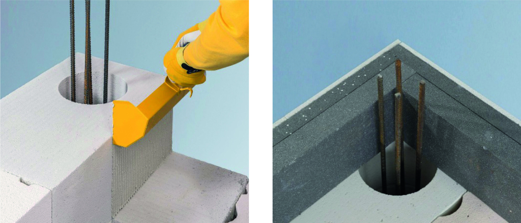
Figure 2 illustrates the application of formwork blocks for permanent formwork, achieved by reinforcing and concreting the column openings. The blocks are reinforced with shear and longitudinal reinforcement and concreted in sections as the walls are constructed. The final concreting stage is carried out alongside the floor slab above. In principle, the columns can be connected to the slabs with or without transferring vertical loads. A coupled configuration is advisable when the vertical load level in the wall needs to be reduced, as in multi-storey buildings. This construction method relieves the masonry walls adjacent to the reinforced concrete columns of vertical load, which makes it easier to verify their load-bearing capacity under vertical loads. However, if seismic effects occur and horizontal loads are applied, a significant reduction in vertical load will result in a loss of horizontal load-bearing capacity in the wall. Therefore, a decoupled configuration with a polystyrene separating layer might be used for walls requiring larger shear transfer (e.g. low-rise buildings). In this case, the vertical loads remain on the wall and additional corrosion protection of the reinforcement at the connection point is recommended (e.g. galvanized steel). By deliberately and regularly arranging additional reinforcement elements, the columns contribute to the structural bracing in the form of tension and compression members and improve the desired box behaviour of the structural system.
Design
Design principles for confined masonry in accordance with EN 1996-1-1 [2] can be used to verify the performance of shear walls with columns in formwork blocks under shear, bending and/or axial load. When verifying bending and axial load for such walls, the contribution of the concrete columns within the formwork blocks in compression can be disregarded. Shear walls are verified based solely on design values for axial load-bearing capacity derived from masonry, with reinforcement considered only in the tension zone. As a conservative approach, the shear resistance of the columns is disregarded when verifying the shear strength of wall panels with embedded columns. The shear capacity is calculated using the full wall length rather than the compressed length typically used for unreinforced masonry panels since the columns prevent the wall from gapping or separating by providing confinement.
Constructive rules
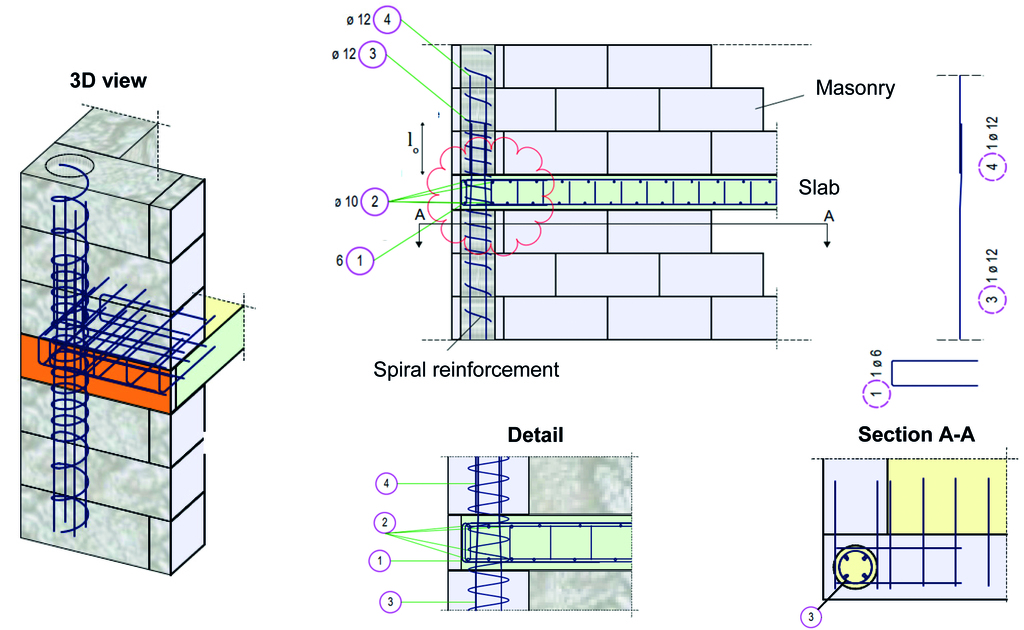
The reinforced concrete columns integrated into the formwork blocks must be designed to act as tension members. Additionally, when seismic design is performed in ductility class DCM (behaviour factor q > 1.5), the structural requirements of EN 1998-1 [3] must be considered. The reinforced concrete columns and their slab connections must be structurally designed using internal design forces in accordance with EN 1992-1-1 [1] and EN 1998-1 [3]. The following structural requirements for in-situ circular concrete columns regarding geometry, longitudinal reinforcement, and shear reinforcement according EN 1992-1-1 [2] must be considered:
· Geometry: d ≥ 20 mm
· Longitudinal reinforcement
o dsl ≥ 12 mm with spacing sl ≤ 300 mm
o Arrangement according to EN 1992-1-1 [1]
· Shear reinforcement with spiral stirrups
o ds,bü ≥ max (dsl/4 ; 6 mm) with spacing sbü ≤ min (12 dsl ; (min b; h); 300 mm)
o Anchorage with standard hooks in accordance with EN 1992-1-1, 9.5.3 [1]
Figure 3 shows an example of an appropriate structural configuration with spiral and longitudinal reinforcement for a continuous column integrated into the floor slabs.
Earthquake resistant connection of partition walls
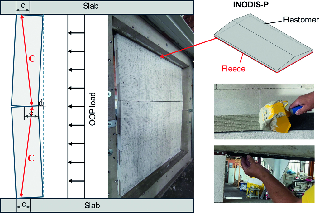
Due to significant earthquake-related damage to partition walls, the next generation of Eurocodes will require their performance under seismic actions perpendicular to their plane to be verified. This includes both the walls themselves and their connections to floor slabs or frames. The connections between the partition and the surrounding structural frame must be capable to resist the resulting horizontal forces caused by lateral seismic action effects. These connections should be distributed regularly along the perimeter of the partition, either on all sides or at least on two opposite sides. As the tensile strength of masonry cannot be considered, the bending stress in partition walls can only be verified by assuming an arching action within the wall, for which a stiff connection between the wall and the slab is required. The required rigid connection is usually achieved by grouting the joints at the base and top of the wall with full-surface contact using general-purpose masonry mortar with a characteristic compressive strength of 2.5 N/mm2 or thin layer mortar. However, in practice, this usually results in an inadequate filling due to mortar slipping through, uneven joint widths and the time-consuming nature of the process. If the remaining gap is filled with assembly foam, mineral wool or flexible acoustic profiles the result is a hinged (non-rigid) connection. In seismic regions, such hinged connections are only suitable to a very limited extent due to the low bending resistance of partition walls.
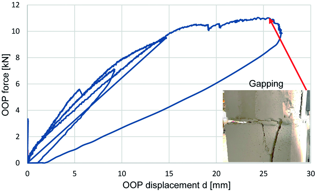
Figure 4 (left) shows deformation under out-of-plane (OOP) loading, with gapping occurring at mid-height and the formation of a compression arch. This arching effect is characterised by the arching force C and the compressed zones of length c. To achieve this, the walls must be rigidly connected to the floor slabs once the creep and shrinkage effects in the slabs have subsided. A suitable solution would be to use a sufficiently stiff, triangular-shaped elastomer that can be attached to either the top of the wall or the slab. This is installed by applying conventional thin layer mortar to a fleece surface to ensure high bond strength. The triangular shape enables full-surface mortaring from both sides, allowing the formation of the required compression strut. Figure 4 shows the triangular INODIS-P profile, its installation, and the gapping of the partition wall in the central area under out-of-plane (OOP) loading. The wall properties are: thickness 115 mm, height = 2.5 m, AAC blocks with a dry bulk density in the range of 500-550 kg/m³ and a compressive strength ≥ 5.0 N/mm² with thin layer mortar strength class M10. Figure 5 shows the corresponding load-deformation curve, with a maximum load of 11.5 kN and failure of the wall in the compressed cross-section zone at mid-height. Combined with the low weight of the AAC wall, this force corresponds to design ground accelerations of up to 8 m/s² according to EN 1998-1 [3], which covers the range of accelerations experienced in Europe. This seismic resistance was further verified through shaking table tests conducted as part of the ECORE project [4], in which partitions with INODIS-P were able to withstand accelerations of 30 m/s² in a two-storey building.
Application example and results
The application of the concept using formwork blocks at the wall ends is illustrated for the two-storey single-family house shown in Figure 5. The exterior walls are made of 365 mm thick autoclaved aerated concrete blocks with a dry bulk density in the range of 300-331 kg/m³ and a compressive strength ≥ 2.5 N/mm, while the interior walls are constructed from 240 mm thick calcium silicate blocks. Analysis and verification were carried out using the MINEA [5] software package for a maximum spectral acceleration on rock at the building site of SaP,R = 1.94 m/s2. Using only unreinforced masonry results in failure of four ground-floor walls. By using formwork blocks with integrated reinforced concrete columns, a 36% increase in load-bearing capacity was achieved, which allows for a successful verification of structural safety. The installation of non-load-bearing partition walls with a thickness of 115 mm made of AAC blocks with a dry bulk density in the range of 500-550 kg/m³ and a compressive strength ≥ 5.0 N/mm² using the INODIS-P profile is easily possible, since the design seismic acceleration according to EN 1998-1 [3] on the upper floor is 2.1 m/s² and significantly lower than the maximum capacity of 8 m/s² verified through experimental tests [4].

References
[1] Eurocode 2: Design of concrete structures – Part 1-1: General rules and rules for buildings, European Committee for Standardization, 2004.
[2] Eurocode 6 - Design of masonry structures - Part 1-1: General rules for reinforced and unreinforced masonry structures,European Committee for Standardization, 2005.
[3] Eurocode 8: Design of structures for earthquake resistance – Part 1: General rules, seismic actions and rules for buildings, European Committee for Standardization, 2004.
[4] Köber. D., Butenweg, C., Chaudat, T., Miccoli, L., Nomikou, M., Dumitrescu, M., Czaderski, C., Bernauer, F.: Shaking table test challenges for a lightweight concrete structure, 18th World Conference on Earthquake Engineering, 2024.
[5] MINEA: Analysis and design of masonry structures, SDA-Solutions GmbH, Herzogenrath, www.minea-design.com, 2025.
[6] Xella Deutschland GmbH: Ytong Silka – Das Baubuch – Sicher planen und bauen, 6. Auflage, Stand: 06/2023.