Science & Innovation
Positive effect on even pore distribution
Possibilities of waste perlite utilization as sand replacement in AAC production
Loading...
Lenka Mészárosová has been a researcher since 2010 and an Assistant Professor since 2018 at the Brno University of Technology (BUT), Faculty of Civil Engineering, Institute of Technology of Building Materials and Components. In 2017, she obtained her PhD in the field of Physical and Building Materials Engineering. Her areas of interest include building materials, with a specialization in lightweight building materials and a focus on microstructure, mineralogy, particle morphology, use of secondary raw materials, surface protection, durability, etc. She is the author of more than 80 scientific publications in the field of building materials.

Rostislav Drochytka is Dean of the Faculty of Civil Engineering at the Brno University of Technology (BUT). In 2001, he was appointed Professor for the field of Physical and Construction Materials Engineering at the same faculty. In 2013, he received an MBA degree in the field of Strategic Management, Institute of Law and Legal Sciences, o.p.s. In 1989, he was appointed a court expert in the field of economics and construction. Since 1992, he has been Head of the expert institute Stavexis, s.r.o. Since 2001, he has been a member of the International Union of Testing and Research Laboratories for Materials and Structures (RILEM).

Jindřich Melichar has been a researcher since 2013 and an Assistant Professor since 2018 at the Brno University of Technology (BUT), Faculty of Civil Engineering, Institute of Technology of Building Materials and Components. He achieved his Master´s degree in 2012 at the Faculty of Chemistry (BUT) in the field of Chemistry, Technology and Properties of Materials. He defended his PhD in 2018 at the Faculty of Civil Engineering (BUT) in the field of Physical and Building Materials Engineering. His research interests are mainly related to electrically conductive cement-based building materials, 3DCP, waterproofing injection screens, utilization of secondary raw materials, etc. He is the author of more than 50 scientific publications in the field of building materials.

Vít Černý has been a researcher since 2007 and an Assistant Professor since 2015 at the Brno University of Technology (BUT), Faculty of Civil Engineering, Institute of Technology of Building Materials and Components. In the years 2011 – 2015, he was Executive Manager of the Microstructure of Building Materials Research Group at the AdMaS Center of BUT. He defended his PhD in 2012 at the same Faculty in the field of Physical and Building Materials Engineering. His areas of interest are mainly related to AAC, fly ash-based artificial aggregates, cement composites with reduced electrical resistivity, fly ash-clay grouting, the use of secondary raw materials, etc. He is the author of more than 170 scientific publications in the field of building materials.
The aim of this research was to determine possibilities for reducing the density of autoclaved calcium silicate composites using waste expanded perlite as a light filler. The data is expected to inform further research into the use of lightweight filler in both calcium silicate composites and AAC.
The calcium silicate composite of interest is based on the AAC production technology. For clarity, this technology will be briefly described. The basic raw materials to produce AAC are lime, silica sand and water. Cement, gypsum and aluminium powder are also used. Lastly, other additives may be used, depending on the manufacturer. The raw materials are mixed to form a fluid mixture to which aluminium powder is added at the end of the mixing process. The liquid mixture is then poured into the mould. During the reaction of the aluminium powder with lime and water, hydrogen gas is produced, thereby aerating the liquid mixture. In this way, the concrete obtains its typical porous structure. After demoulding and cutting the green body mass to the desired size, the material is ready for curing. Autoclaving is performed in an autoclave at 180-190°C for 7-12 hours at a pressure of 1.2-1.4 MPa (the temperature, time and pressure of autoclaving vary by manufacturer). During autoclaving, chemical reactions take place in the microstructure of the AAC, giving the resulting products their strength. After curing, the products are immediately ready for dispatch [1-3].
To understand the changes in microstructure, it is first necessary to describe the basic mechanisms of calcium silicate hydrate formation (CSH). The basic raw materials for the production of calcium silicate composites are lime and quartz sand. These materials are characterized by their oxides. Lime is a carrier of calcium oxide (CaO) and silica sand contains a high amount of silica dioxides (SiO2). The last important component for the formation of the CSH phase is water. However, the interconnection of these three components after mixing is not simple. The silica dioxides contained in the sand are in crystalline form, i.e., they are insoluble and under normal conditions their reaction is weak and contained to the grain surface. Therefore, it is necessary to cure the composites under hydrothermal conditions. During curing, SiO2 reacts with CaO and H2O to form CSH phases. However, the CSH phases can take different forms, each form depending on the specific temperature, curing durations and the ratio of individual oxides. For calcium silicate composites, the CSH phase consist of tobermorite, a layered mineral in the form of long needles, which connects individual grains of unreacted sand and ensures the strength of the product [4 - 7].
The effect of waste perlite on the calcium silicate composite is an area almost unexplored. Perlite is an amorphous volcanic rock that can be classified as a natural pozzolanic material due to its glassy structure and high contents of silica dioxides and alumina oxides [8]. It is these two oxides, alumina oxide and silica dioxide, which are important for the use of waste perlite in the technology of autoclaved calcium silicate composites. During perlite formation by rapid cooling of ejected material in the water medium, about 5% of the water is bound to the rock that is used in the production of expanded perlite. Perlite is heated to a temperature in the range of 900-1000°C, which converts the contained water into steam. As a result of the expansion of the material, expanded perlite is formed which has a 4-20 times higher volume [8 – 11], which also increases the specific surface area. Consequently, expanded perlite is a very porous material and thus a good thermal insulator. Waste perlite is characterized by low density, fire resistance and resistance to fungi and algae [9]. During the production of expanded perlite, waste perlite is formed, which belongs to the waste category "O" [12, 13]. It can be further recycled, used as a secondary raw material, or deposited in construction waste dumps. Kotvica et al. [13] utilized ground expanded perlite as an additive to cement and increased compressive strength by up to 50% at 35% substitution. Further research has found that waste perlite is suitable for zeolite synthesis and suppresses alkali silica reaction when used in cement [13 - 14]. In AAC, waste perlite was used as a substitute for quartz sand, and a 10% substitution resulted in a 15% reduction in thermal conductivity [1]. The possibility of using waste perlite is also confirmed by other studies dealing with the use of expanded perlite in AAC and fly ash-lime-gypsum mixtures [15, 16].
Materials
Quartz sand, waste perlite, quicklime, cement, gypsum, aluminium powder and water were used to prepare the reference sample. The basic chemical composition of the quartz sand (CZ, Dolní Lutyně) and waste perlite (CZ, Šenov u Nového Jičína) is shown in Table 1. The lower content of SiO2 in waste perlite is compensated by the fact that a large part of this oxide is in amorphous form. The amorphous form has easier solubility in hydrothermal conditions, compared to the crystalline form. The granularity of quartz sand can be defined as 100% passing and that of waste perlite as 80% passing through a 0.2 mm sieve. The volumetric weight of the waste perlite was 150 kg/m3. Quicklime (CZ, Beroun) labelled CL 90-Q (R5, P1) according to ČSN EN 459-1 "Building quicklime" was used, as well as Portland cement CEM I 52.5 N (SK, Rohožník). The flue gas desulfurization (FGD) gypsum contained at least 95% calcium sulphate (CZ, Dětmarovice).
Table 1: Chemical composition of siliceous materials used
SiO2 | CaO | Al2O3 | MgO | K2O | Na2O | |
Quartz sand | 92.9 | 0.23 | 2.53 | 0.16 | 1.5 | 0.7 |
Perlite | 74.0 | 1.26 | 13.1 | 0.23 | 4.5 | 2.1 |
The tested mixtures were based on the basic raw material composition of AAC. This is a mixture without overgrowth sludge or other additional raw materials. Quartz sand was substituted with waste perlite using replacement levels of 10%, 30%, 50% and 100% by volume (Table 2). The determined water absorbing capacity of the waste perlite was 260%. For this reason, the dose of water was proportionally adjusted. To achieve the required pore structure, 0.02% aluminum powder was used.
Table 2: Composition of AAC with replacement of sand by waste perlite in doses of 10, 30, 50 and 100%
Sand/Lime ratio | Lime | Cement | Calcium sulfate | Quartz sand | Perlite |
[%] | |||||
100:0 | 7.6 | 12.6 | 3.5 | 76.4 | 0.0 |
90:10 | 7.6 | 12.6 | 3.5 | 68.8 | 7.6 |
70:30 | 7.6 | 12.6 | 3.5 | 53.5 | 22.9 |
50:50 | 7.6 | 12.6 | 3.5 | 38.2 | 38.2 |
0:100 | 7.6 | 12.6 | 3.5 | 0.0 | 76.4 |
Preparation of test samples
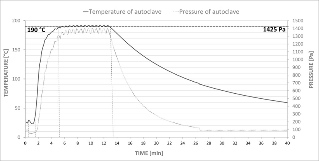
For the production of the AAC, the dry reactive components (lime, cement), sand suspension (sand, gypsum, water) and aluminium suspension (powdered aluminium, degreasing agent, water) were first homogenized separately. Subsequently, the sand suspension was preheated to 40°C. The preheated sand suspension and the dry reactive components were mixed for a duration of 60 s. The aluminium suspension was added last. The resulting mixture was stirred for an additional 30 s. The mixture was poured into 6 plastic moulds (100 mm cubes). After 24 hours, the AAC blocks were placed in an autoclave. The autoclaving temperature was set to 190°C and the time under hydrothermal conditions was 7 hours. These conditions correspond to real AAC production.
Results and discussion
Flow properties
As part of determining the dominant parameters of the tested mixture, a flow test was first performed. The mixture contained a water dose corresponding to the optimal flow of the reference mixture (24 cm). Furthermore, an extra dose of water was added, corresponding to the difference in the absorbency of waste perlite and silica sand. Subsequently, the influence of the perlite admixture on the spillage of the mixture was monitored. At a low viscosity of the mixture, the hydrogen gas formed does not bind to the microporous binder matrix and the gas escapes from the mixture before it hardens. Imperfect aeration also occurs at too high viscosities. In such a case, the hydrogen gas is incompletely dispersed in the AAC suspension, and the high pressure of the microporous binder matrix flocculates the gas. This creates large pores, and the porous concrete loses its thermal insulating property [17]. The results of the flow test are shown in Figure 2.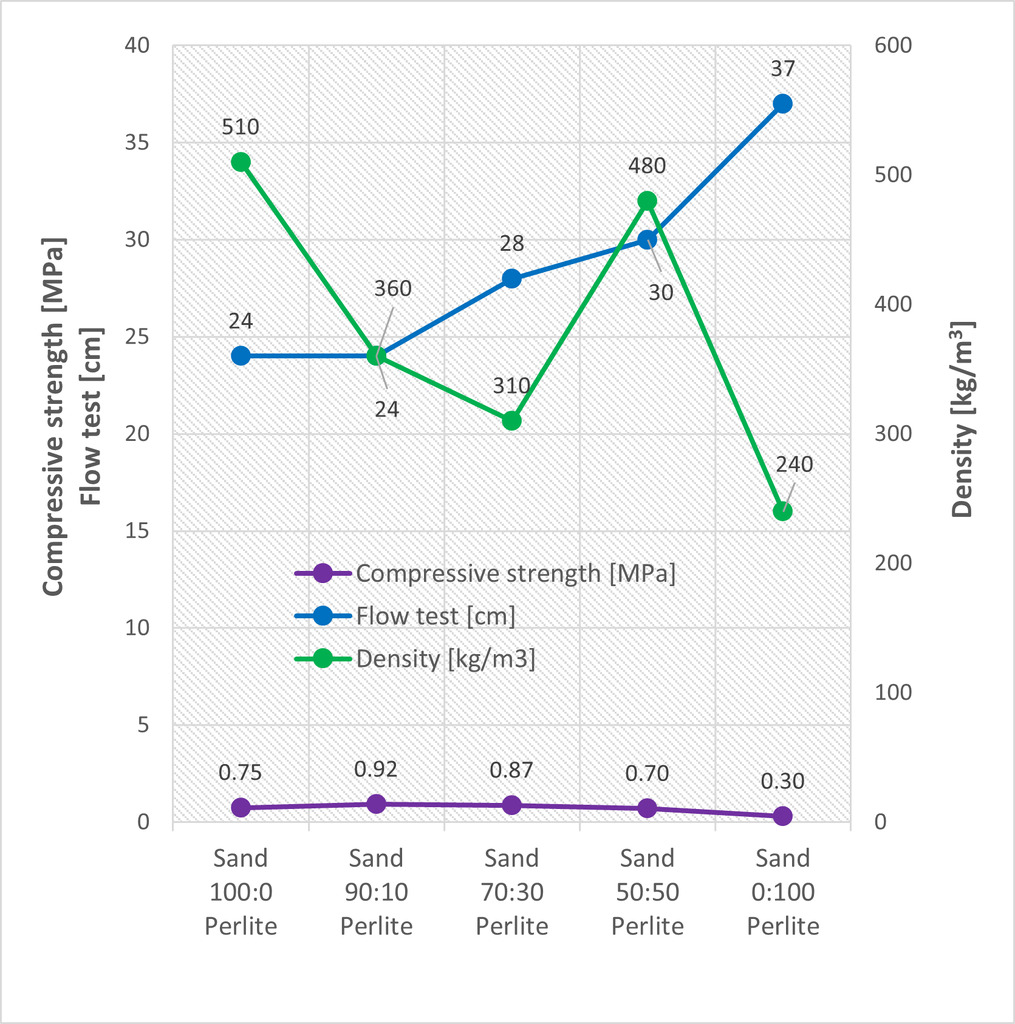
The influence of the amount of waste perlite on the consistency of the mix can be observed from the flow test. As waste perlite substitution of sand increases, the viscosity of the mixture decreases. This dependence was observed from 30% substitution levels. The addition of 10% waste perlite had no effect on the consistency.
Density and strength
The effect of waste perlite substitution levels on density and compressive strength was monitored (Fig. 2). The compressive strength of the samples with waste perlite increased by up to 22% compared to the reference sample. The density decreased with 10% and 30% substitution with waste perlite. From a waste perlite content of 50%, the strength started to decrease. However, the density increased significantly with 50% silica sand substitution. This phenomenon is related to the leakage of hydrogen gas prior to hardening of the microporous binder matrix and was further confirmed by the porosity results (Fig. 4). With a 50% waste perlite substitution, a decrease in the total pore content as well as a decrease in the average pore size was observed. Therefore, it can be concluded that the viscosity of the mixture was too low, and the gas easily left the fresh mix. The 100% waste perlite sample had the lowest density, which was not only related to total replacement of silica sand with a material of very low density but also to the formation of large pores (Fig. 3).
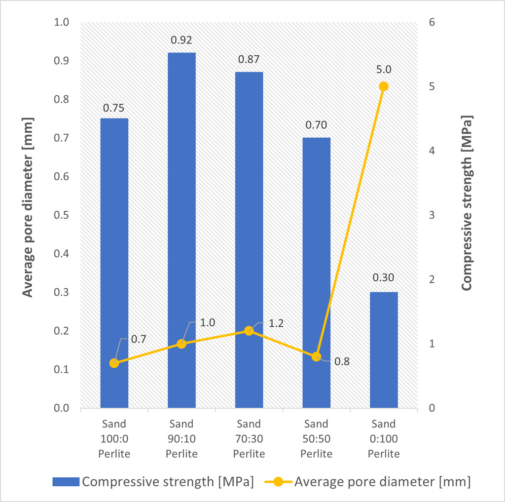
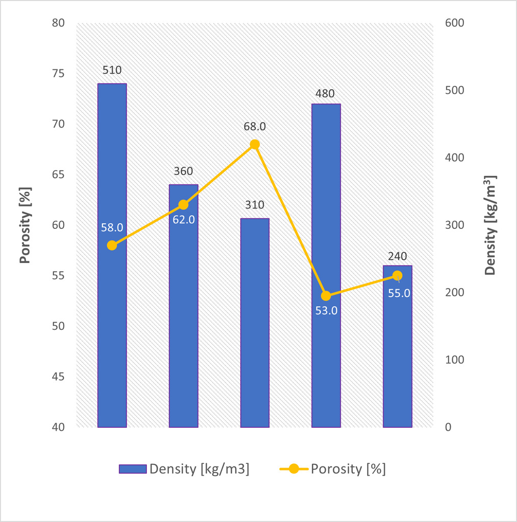
The created porous structure was inspected with an optical microscope. The total amount of pores in the reference sample was 58% (Fig. 4) and their average size was up to 1 mm (Fig. 3). Macropores in AAC, defined from a size of 0.06 mm, significantly affect the physical-mechanical properties. At 10% and 30% substitution with waste perlite, the total porosity of the sample and the average pore size increased. In correlation with an increasing porosity, the density of the sample also decreased (Fig. 4). However, the compressive strength increased with lower density and higher porosity. This statement applies to samples with 10% and 30% waste perlite substitutions. The increasing strength is likely related to the microstructure of the sample as described below. The different pore content and size is present only in the sample with a 100% substitution of quartz sand.
Microstructure
As described in the introduction, it is necessary to identify newly formed minerals to explain the properties of AAC. In this case, the focus is on the mineral 1.1 nm tobermorite, which is a carrier of the strength. The microstructure of the AAC was determined by X-ray diffraction analysis. In this analysis, it is possible to determine the degree of crystallization of the new phases using the intensity of the diffraction line (Fig. 5, left). The hydrothermal conditions were adjusted such that the quartz surface was partially dissolved and released H3SiO4- or H2SiO42- ions into the alkaline solution. These ions react with Ca2+ ions present in the alkaline solution to form crystalline calcium hydrogen silicate phases. For this reason, crystalline 1.1 nm tobermorite or other crystalline phases should appear in all samples.
The results of the XRD analysis show that with increasing substitution of silica sand (crystalline quartz) with waste perlite (amorphous quartz), the peak of 11A tobermorite increases and the peak of quartz and muscovite decreases. These minerals are contained in the sand. At 50%, the crystallization of tobermorite was most intense. It can be described as an optimal combination of crystalline and amorphous SiO2. No tobermorite was noted in the sample with 100% waste perlite. However, there were other new phases. The sample contained α-C2SH, which decomposes during curing at the expense of 1.1 nm tobermorite. The results of the XRD analysis confirm the conclusions of previous works, where a mixture of crystalline and amorphous SiO2 is the optimal variant. [18].
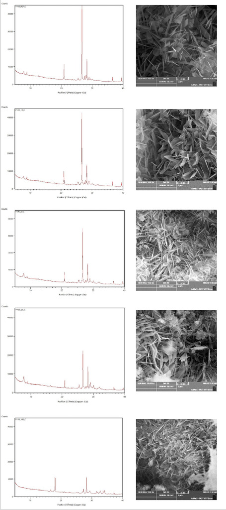
SEM images of the minerals are shown in Figure 5 on the right. The AAC contains plate-like 1.1 nm tobermorite crystals. This shape of tobermorite is most often found in the crystalline quartz reaction. At 10% and 30% sand substitution by waste perlite, the shape “house of cards“ of 1.1 nm tobermorite described by Chucholowsky [19] occurs. This shape of tobermorite supports the compressive strength, which has been confirmed here. The AAC with 100% substitution does not contain 1.1 nm tobermorite crystals and contains long new phases. This phase is called α-C2SH and is formed as the first reaction product using 0.10-1.00 mm grain silicon source [20].
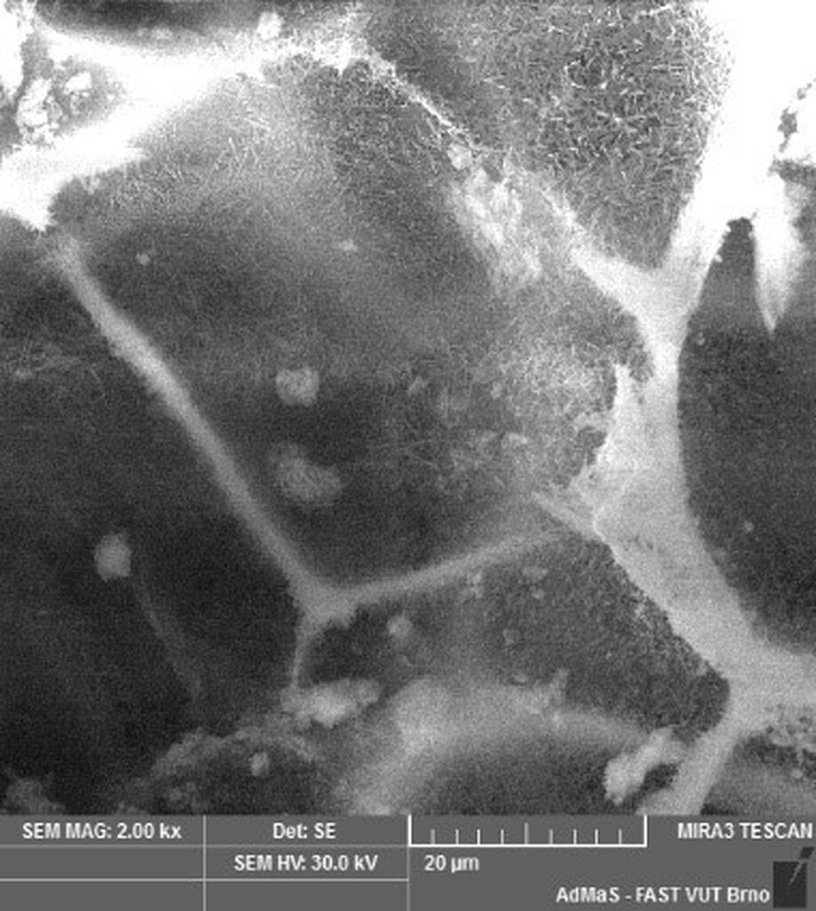
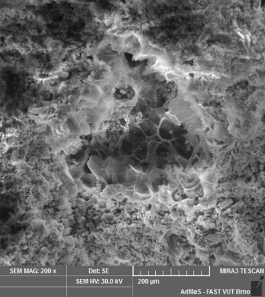
As part of studying the structure of AAC with a high proportion of waste perlite, images were taken that illustrate the incorporation of perlite into the structure of the cement composite (Fig. 6).
Conclusion
The results of this study show that the maximum beneficial substitution amount of waste perlite is 30%. Up to this limit, waste perlite has a positive effect on the distribution of pores in the AAC matrix. The compressive strength of the samples with waste perlite increased by up to 22% compared to the reference sample. It is positive that this increase in compressive strength was accompanied by a simultaneous decrease in density. AAC using waste perlite has a high potential as an insulation material for buildings.
Acknowledgement
This research was completed with the financial support of the Czech Science Foundation (GACR), Standard project No. 23-04824S “Influence of alternative raw material components on improvement of physico-mechanical properties of aerated autoclaved concrete”.
References
[1] Ling, T., Mo, K. H., Qu, L., Yang, J., & Guo, L. (2017) Mechanical strength and durability performance of autoclaved lime-saline soil brick Const. Buil. Mat 146 403-409.
[2] Dachowski, R., & Nowek, M. (2016) Landfill leachate as an additive in sand-lime products Proc. Eng. 161 572.
[3] Pytel, Z., & Malolepszy, J. (2000) Effect of mineral admixtures on some properties of sand-lime bricks Elsevier 371-382.
[4] Kurama, H., Topcu, İ. B., & Karakurt, C. (2009) Properties of the autoclaved aerated concrete produced from coal bottom ash Jour. Mat. Proc. Tech. 209 767-773.
[5] Zou, J., Guo, CH., Jiang, Y., Wie, C., & Li, F. (2016) Structure, morphology and mechanism research on synthesizing xonotlite fiber from acid-extracting residues of coal fly ash and carbide slag. Mat. Chem. Phys. 172 121-128.
[6] Mitsuda, T., (1982) Influence of starting materials on the hydrothermal reaction in the CaO-SiO2-H2O system Jour. Jap. Assoc. Mineral. 77 317-329.
[7] Rozycka, A., & Pichor, W. (2016) Effect of perlite waste addition on the properties of autoclaved aerated concrete Constr. Buil. Mat. 120 65-71.
[8] Kotwica, Ł., Pichor, W., & Nocun-Wczezlik, W. (2016) Study of pozzolanic action of ground waste expanded perlite by means of thermal methods Jour. Ther. Anal. Calor. 123 607-613.
[9] Expandovaný perlit Perlit.cz Dostupné z: http://www.perlit.cz/expandovany-perlit/
[10] Long, W.J., Tan, X.W., Xiao, B.X., Han, N.X., & Xing, F. (2019) Effective use of ground waste expanded perlite as green supplementary cementitious material in eco-friendly alkali activated slag composites Jour. Cl. Prod. 213 406-414.
[11] Sengul, O., Azizi, S., Karaosmanoglu, F., & Tasdemir, M.A. (2011) Effect of expanded perlite on the mechanical properties and thermal conductivity of lightweight concrete Ener. Buil 43 671‑676.
[12] Expandovaný perlit: Bezpečnostní list. Perlit.cz [online]. Dostupné z: http://www.perlit.cz/wp-content/uploads/2017/03/bezpecnosti-llist_EP.pdf
[13] Kotwica, Ł., PICHÓR, W., Kapeluzsna E and Rozycka A 2017 Utilization of waste expanded perlite as new effective supplementary cementitious material. Jour. Cl. Prod. 140 1344-1352.
[14] Singh, M., & Garg, M., (1991) Perlite-based building materials - a review of current applications. Const. Buil. Mat. 5 75-81.
[15] Ayudhya, B.I.N. (2011) Compressive and splitting tensile strength of autoclaved aerated concrete containing perlite aggregate and polypropylene fiber subjected to high temperatures Son. J. Sci. Technol. 33 555-563.
[16] Demir, I., & Serhat Baspinar, M. (2008) Effect of silica fume and expanded perlite addition on the technical properties of the fly ash-lime-gypsum mixture Const. Buil. Mat. 22 1299-1304.
[17] Narayanan, N., Ramamurthy, K. Structure and properties of aerated concrete: a review, Cem. and Con. Comp., 22 (2000) 321–329, doi:10.1016/S0958-9465(00)00016-0.
[18] Drochytka, R., Černý, V. (2019) Influence of fluidized bed combustion fly ash admixture on hydrothermal synthesis of tobermorite in the mixture with quartz sand, high temperature fly ash and lime. Construction and building materials, 2019, vol. 230, no. 2020, p. 1-11. ISSN: 0950-0618.
[19] Chucholowski, C., Holger, H., & Thienel, K. (2018) Improving the recyclability, environmental compatibility, and CO2 balance of autoclaved aerated concrete by replacing sulfate carrier and cement with calcined clays Ce/papers 2 503-512.
[20] Harmann, A. (2004) Untersuchungen zum Kristallisationsverhalten und zur Morphologie von 11 Å Tobermorit in Abhängigkeit von der Reaktivität der Kieselsäurequelle und dem Ionenbestand der Hydrothermallösung Fach. Geowiss. Geog. Univ., Hanover.