Science & Innovation
Parametric Masonry Textiles
Post-Tensioned Screen Walls Using Robotically Milled AAC Units
Loading...
www.graftworks.net Instagram @lawrenceblough

www.timburllc.com Instagram @timburllc
Wright: The Textile-Block and Ornamentation
Frank Lloyd Wright developed his concrete block system while reconsidering traditional masonry construction through the logic of modern industrial techniques. Combining prefabrication and composite structures, the system employed concrete block modules and steel reinforcing rods to weave a building as a kind of mechanical fabric. Termed “textile-block” and later renamed the “Usonian Automatic”, double layered walls – with an insulating airspace between – were constructed by stacking thin shell blocks combined with steel rods set in grooves at the vertical and horizontal edges of each unit (Wright, 1957). Filling the channels with grout produced structural continuity and removed the need for mortar at the joints. The resulting steel matrix provided tensile performance, and combined with the compressive strength of the concrete created a lightweight composite system. Wright also fabricated custom forms to exploit the plasticity of concrete to develop ornamental patterns imprinted into the face of the blocks. Coffered on the inside face and frequently perforated with inset glass, the tessellated walls and grille work were constructed out of 16” square x 3 ½-inch-thick blocks. Precast in the field, Wright’s aim was that the blocks be economical to fabricate and the system easy to assemble without highly skilled labor.
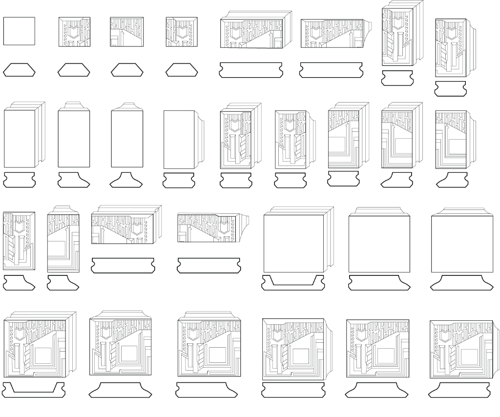
Enmeshed within the relief pattern that propagates across its surfaces at many scales, the part to whole relationships of the system is consistent with Wright’s theory of an organic architecture, constituting a tectonic unique to its constructive logic. Through the agency of the machine, Wright transposed these ideas for the twentieth century attempting “to derive an authentic ornament from the process of fabrication, irrespective of whether this entailed the mechanized manufacture of basic building blocks or the systematic assembly of prefabricated elements” (Frampton, 1991).
Design Process: Techniques and Parameters
The research studio set out to investigate the form finding, structural and assembly logics of autoclaved aerated concrete in order to develop innovative masonry screen wall systems for low to mid-rise buildings. Working in teams, students designed assemblies using varying unit shapes to be fabricated by a 6-axis robotic milling process. A generic office building was the foil to produce new over-cladding strategies to alter the aesthetic, environmental, and programmatic performance of the existing structure. Parametric design and digital machining processes were harnessed to produce novel tectonics while simultaneously working within the exigencies of a rational construction system with real world applications. Because AAC units are easily cut or shaped, a range of construction modules and ornamental relief patterns can be produced economically and quickly, using standard stock without the need for custom molds.
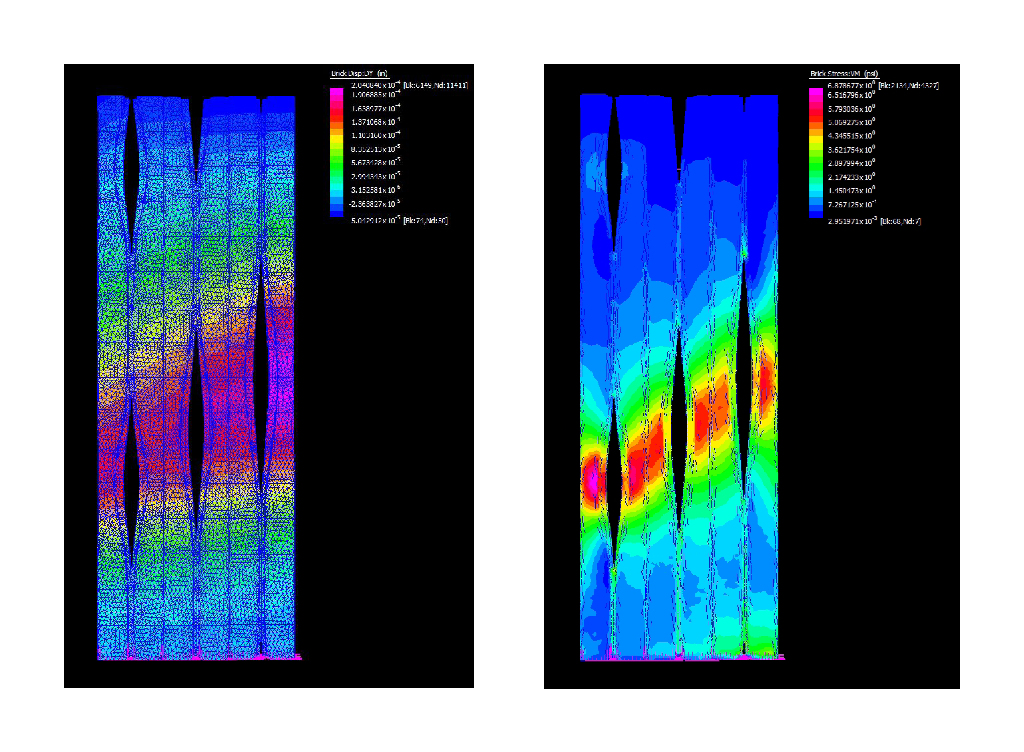
The studio was supported by parametric software workshops to meet the demands of the brief, along with a façade and structural engineer who consulted during pin-ups to aid in the technical development of the research. In addition to in-class exercises and critiques, students traveled to an off-campus fabrication facility operated by Timbur LLC to see a demonstration of the robotic setup and milling process. Aercon Florida LLC, one of the largest AAC manufacturers on the US east coast, sponsored the research and donated several pallets of the material for the investigation.
Students began their design strategies for a masonry screen wall using both analogue and digital modeling techniques at multiple scales. Working with the constraint of a given module size, they were asked to develop “thick 2D” porous surface assemblies that modulate light, air, and view. Considering the specific material qualities and workability of AAC, they had to invent an operating system of simple bottom-up transformations, e.g., rotation, reflection, subtraction, corbelling, and oblique cutting that created larger scale surface patterns and organizations. In parallel with wire cut foam models (up to 6 blocks) studying module to module joining logics, digital models in Rhinoceros3D software (up to 24 blocks) were made that investigated surface geometry. A final exercise exploring larger field organizations populated over the entire facade were tested by producing high-density foam prototypes flip-milled on a 3-axis Techno CNC router. Some schemes emphatically emphasized the module as a constituent characteristic of the organization. In others, the module was suppressed in service of a larger pattern at the scale of the building. In all cases it was demanded that that pattern be continuous across joints, creating catalytic relations among the blocks, where the whole exceeded the sum of its parts.
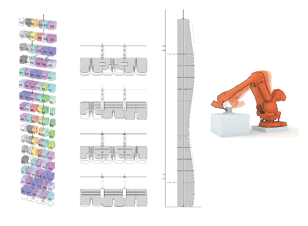
Seven initial parameters were part of the brief providing tectonic specificity to the assembly system: 1) modules were to be made from standard 8x8x24-inch blocks 2) modules could not be smaller than 4-inch in any direction 3) modules had be stacked vertically, horizontally or diagonally to form a bearing surface 4) modules could be removed to produce porosity but required a 4-inch bridge 5) larger openings up to 4-feet required an 8-inch bridge with a lintel or arch 6) modules could be cantilevered to produce corbelling but a 2/3 back span had to be provided 7) a minimum of 30% of the screen wall had to be open to light and air. Considerations such as gradation and concentration, tessellation logics, position vs. mutation of the module, unique vs. repetitive block types, and bond type created a family of different but related proposals and effects.
The research included the development of the wall section of the building as a specific location of inquiry. This was critical not only to study the exigencies of the assembly system but to discover the spatial potential between the screen wall and the existing structure. Simple programmatic pressures from both the interior and exterior of the building created inflections in the wall surfaces and problematized where the conditioned space begins and ends. Conditions such as view, light control, circulation, threshold, and negotiating the corner added another set of variables to the organizations. Finally, students were asked to develop 3D assembly diagrams of their proposal to identify component to component connections and reinforcing strategies.
Prototype: Robotic Milling and Assembly
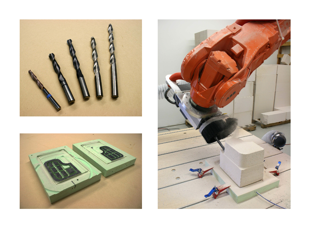
Because the School of Architecture did not have a robot online at the time, Timbur LLC provided the expertise and equipment for fabrication of the AAC components. The full-scale prototype was carved with a reconditioned ABB IRB6400 industrial robot formerly used in the automotive industry. Equipped with an S4C+ controller, the end of arm tooling (EOAT) used a 10 HP HSD milling head to cut standard AAC blocks into custom components. Toolpaths were a function of a two-part workflow, as 5-axis machine operations generated in Rhinocam were converted into polylines and fed through a robotic simulation and programming software called HAL. Developed by Thibault Schwartz, HAL is a plug-in software used for the programming and control of industrial robots. It runs inside of Grasshopper, a visual parametric programming plug-in which runs inside of the Rhinoceros3D modeling platform. The function of HAL is to establish a robot definition – a geometric/kinematic model – that guides a user defined tool through a local coordinate system based on parametric location and orientation data provided by the programmer. This toolpath information is then exported in RAPID, the native ABB programming language, and is run directly from the robot controller.
The promise of this nested workflow is that programming language producing variation in the surface geometry of the façade can be linked to the fabrication code for output of the blocks. In this case, since the set of parameters that guide the overall form from block to block are common, it’s a matter of degree of difference from the geometry of one block to the next. Thus, each block could be unique with the process being automated relatively easily through the programming code. The biggest concern when developing the fabrication process was being able to understand the local parameters of how the material behaved when it’s being milled, and simultaneously manage the global parameters of the entire assembly so all of the components can be accommodated by the robotic setup. A good deal of time was spent considering the small steps in the process, e.g., the way the block is held down on the table when being milled, the cutting envelope of the robotic arm and its reach, and how long of a tool is required to carve the blocks. All of these factors come into play when the range of possible shapes are considered; but after trial and error, it was concluded that once the setup was worked out, the time to produce unique blocks was not significantly different if all of the blocks were the same.
Early in the fabrication process – for efficiency in programming and machining – it was determined that an “in the round” strategy for fabrication would be implemented. The robot – outfitted with a 6-inch long ball endmill – would make a series of parallel circumscribed passes along the Z-axis around each block. In order to accommodate the table and fixture, a 15-degree tilt angle was used on all blocks. Special attention was placed on tool length selection in both design and production. Too long of a tool produced an undesired amount of chatter or vibration during machining, and too short of a tool would not allow adequate clearance for the robotic arm, EOAT and dust collection equipment. One of the biggest obstacles in producing the blocks was development of a “hold down” system for the AAC that allowed unimpeded access to all five exposed sides of each piece of stock. After numerous tests with different substrate and gasket materials, it was determined that under a deep vacuum, blocks could be held in place by a custom milled high-density urethane foam jig. In order to maintain a vacuum to compensate for the porosity of the AAC, a medium-density neoprene sheet gasket was adhered to the jig. Based on the use of mirrored and typologically consistent geometry, all blocks could be manufactured using only two consumable jigs. As the blocks were milled from largest to smallest, the effective area of the vacuum jig was slowly eaten away.
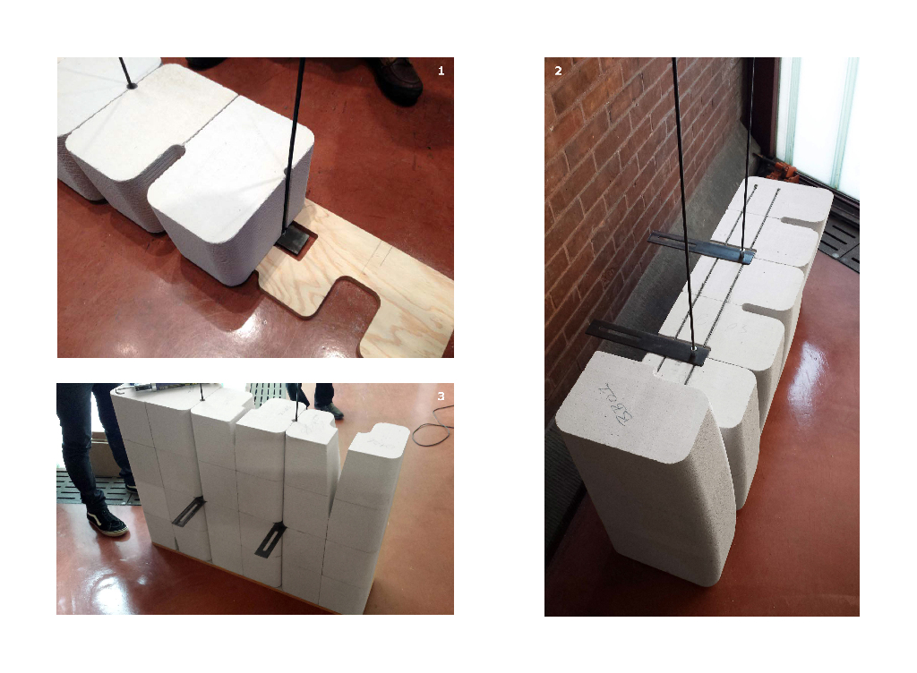
Working with structural engineer Robert Otani, we were able to develop assumptions using analytical design for reinforcing strategies of the AAC screen wall systems. Typically cored every 4-feet to receive vertical or diagonal 5/8-inch threaded rods, post-tensioning allows the wall to resist bending forces and could potentially work as a pre-stressing element. Depending on the geometry, the walls would also require horizontal reinforcement at every other course. The entire assembly would be laid with a thin-bed adhesive mortar making a monolithic wall system. To resist wind load, an 8-inch single wythe screen wall would be tied back to the building structure at every floor, and a double wythe system at every other floor.
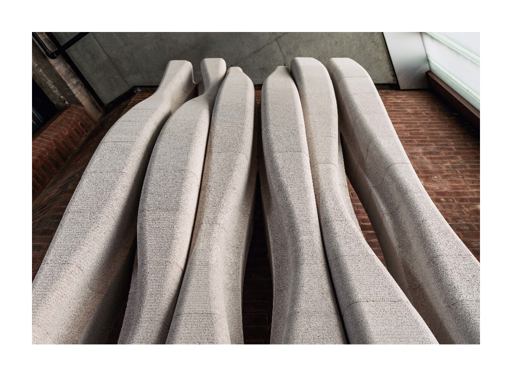
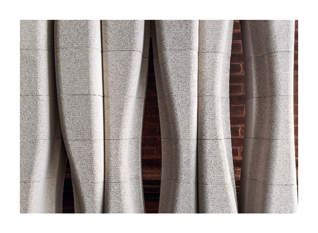
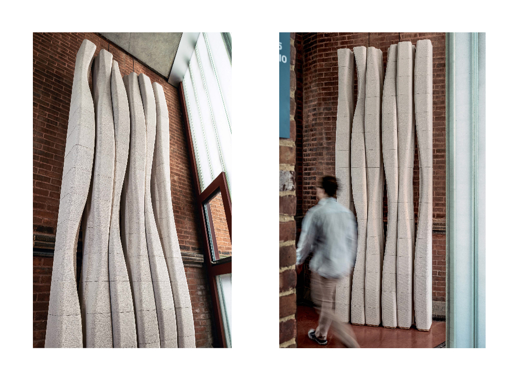
For the full-scale prototype, a scheme was selected from the design studio to develop for installation in the School of Architecture. Otani engineered the system, and several adjustments were made to accommodate the scale and interior location of the assembly but still provide a realistic test of the concept. Comprised of 96 components with 20 unique block types, a 10-feet 8-inch tall by 4-feet wide prototype was constructed adjacent to an existing load bearing brick wall in the lobby. Blocks were milled from 8x8x12-inch stock to create a single wythe screen wall varying in depth from 8-inches to 12-inches. Each block took approximately 20 minutes to fabricate using the robotic setup. Channels were milled into the faces of pairs of blocks to create 1-inch cores for ¼-inch threaded rods located 16-inches on center. The rods passed through holes in slotted steel plates located 2 courses from the top and bottom of the assembly. Bolted to steel angles, the plates were tied back to the existing brick wall with masonry anchors epoxied into the substrate. The rods were then tensioned at plates at the top and bottom of the screen wall. Horizontal reinforcement was accomplished by routing a pair of channels into the top face of the blocks at every fourth course, to accommodate 1/8-inch steel rods that were turned down at the ends and embedded into holes of the stock. For speed of assembly and ease of workability, high performance polyurethane construction adhesive was applied to the bed and head joints of each block.
Conclusion
Building enclosure systems that produce geometrically complex and intricate surfaces are practicable when approached through a component logic that exploits the unique qualities of a given material system (Blough, 2012). Within a limited set of parameters, innovating within the economies of both digital fabrication and traditional assembly logics, the research presented here proposes a construction system that is expressive, flexible, and cost effective guided by the unique qualities of autoclaved aerated concrete. In the last 20 years, there has been renewed research in tectonics and constructional techniques, where the traditional concepts of craft and the joint that were once married to the hand can be rediscovered through the agency of mass customization. This includes the potential to quickly prototype across scales, where each consecutive model becomes a rehearsal for the realities of one-to-one construction. Digital models with a high degree of specificity can be used to test structural performance, develop parametric assembly logics, output templates and component lists, and produce CAD/CAM files for digital fabrication. In this way, traditional building technologies can be reevaluated and updated. This paper advocates a hybrid approach – the standardized AAC system can be made to deliver far more formal variation and structural performance through digital fabrication processes, while capitalizing on its workability and ease of assembly using conventional building practices. The application and intensity of these processes can be tailored to different economies affected by location, budget, labor pool and available construction technology.
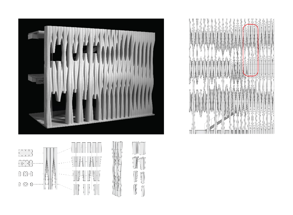
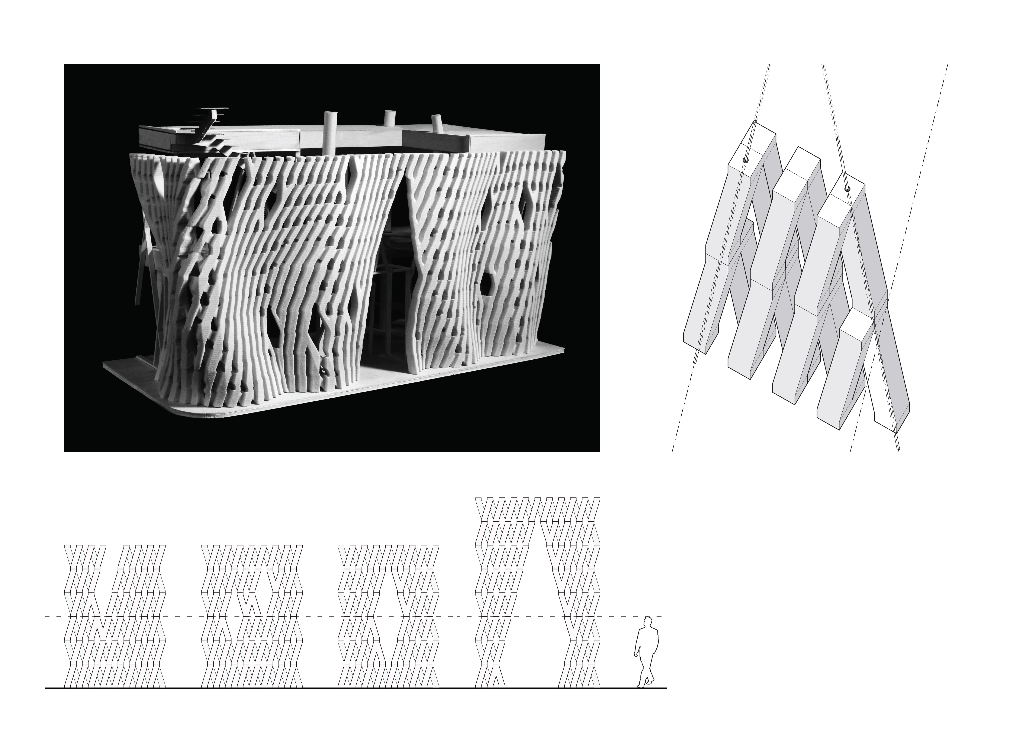
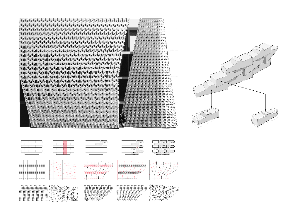
Building facade retrofits have moved to the forefront of the architecture and engineering professions reconditioning aging building stock to improve energy performance, thermal efficiency and update aesthetic value. From the design research produced to date and from the consulting engineers input, we can speculate on how the construction industry could implement the proposed AAC systems for low to mid-rise buildings. Because the blocks are easily carved into custom shapes, they can be robotically precut to create unique geometric surfaces. Prefabricated panels that are post-tensioned can then be economically fabricated in the factory with a high level of quality control. Installed in the field and spanning from floor to floor, panels would be stacked to create a unitized façade system. Being that the blocks are available up to 40-inches in length and are relatively lightweight, wall systems can also be assembled quickly on site using a mini-crane following conventional masonry techniques. For efficient sorting, location, and positioning of the components in the factory or field, RFID tagging would be incorporated – commonly used by the construction industry for precast systems – to manage complex building geometries. Finally, automation could be pushed to the extreme by incorporating robotically controlled processes to assemble intricate AAC block panels by picking, mortaring and placing the custom components in sequence.
This work was made possible with generous support from Aercon AAC and Pratt Institute School of Architecture Dean’s Office
Design Directors: Lawrence Blough and Ezra Ardolino
Design and Assembly Team: Jonathan Cortes, Rena Cukurova, Gary Lee, Alexander Morpurgo, Cameron Reid, Georgia Reyes
Structural Consultant: Robert Otani
Fabrication: Timbur LLC

References
Blough, L (2012). “Digital Tracery: Fabricating Traits”. Matter: Material Processes in
Architectural Production, 357-377, New York: Routledge
Frampton, K (1991). “The Text-Tile Tectonic”. Frank Lloyd Wright: A Primer on
Architectural Principles, 124-149. New York: Princeton Architectural Press
Wright, F.L. (1954). The Natural House, 199-203. New York: Bramhall House