Calcium Silicate Special & Drymix-Special
Innovative and promising approach
Automated construction of calcium silicate masonry by cable robots
Loading...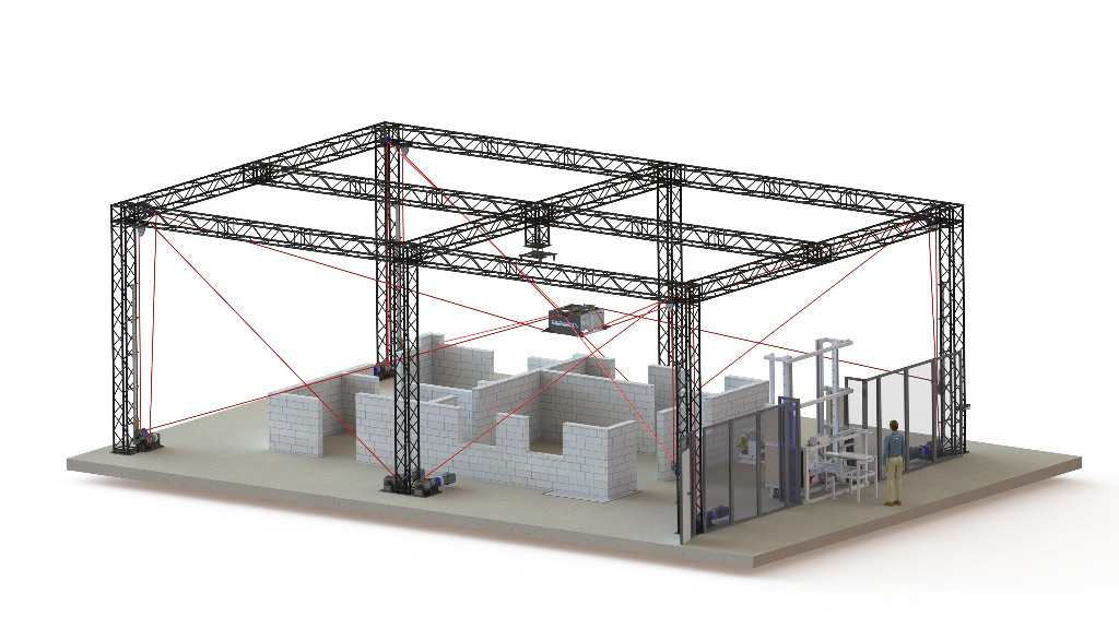
In order to prove the overall process, it is planned to bring the individual results together in one functional model in spring 2021. The focus will be on interfaces between digital building model, cable robot and mortar application device, as well as the interaction of construction site processes and logistics.
Robot suitable masonry construction
The use of medium and large-format masonry units or elements in the thin-bed method and without mortering of the butt joints is state of the art in masonry construction for many years. The proportion of large plane or raster elements with a layer height of ≥ 50 cm is increasing for several years up to 50 % of the whole calcium silicate unit production. The construction of the joints is usually carried out with butt joint technology. Thus, walls and wall sections can be constructed one after another and an optimal construction procedure can be ensured.
In the conception of the here presented automated masonry construction with cable robots has to be considered, if the preliminary considerations can simply be transferred. Concerning the masonry unit formats applies, that the use of larger masonry units enables to increase the buildable wall surface per stroke and the construction progress. It also applies to automated masonry with a cable robot that the buildable wall surface per stroke increases with increasing size oft the masonry unit. But it should be noted that the forces within the components of the cable robot (frame, cables, engines, etc.) will significantly increase and the possible offset speeds could possibly decrease because of the increasing size and weight of the masonry units. Therefore, larger masonry units require a more massive design of the different cable robot components. This contradicts the aims of easy assembly, disassembly and transport of the cable robot.
Considering all these aspects calcium silicate units with a layer height of 25 cm were chosen for the sample building to be built as part of the project. The masonry units will be used, as usually for this kind of units, with thin-bed method and without mortaring of the vertical joints.
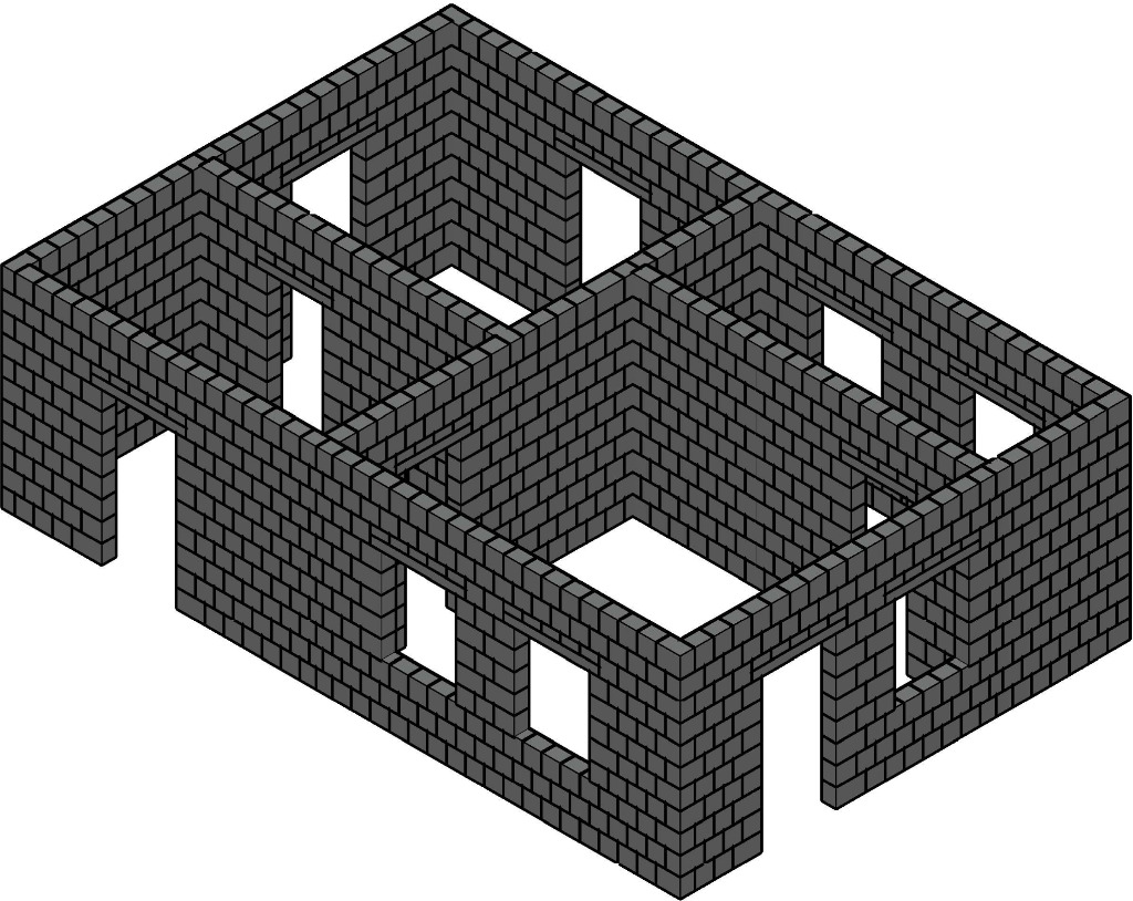
Building different walls section by section and the connection of the walls with butt joint technology are unsuitable to be used for unit-laying with a cable robot because of collisions between already constructed walls and the platform of the cable robot. In contrast to the conventional construction process, masonry construction with a cable robot will be most efficiently, if the whole building layout will be built in layers. The paths along which the units are led by the cable robot thus can be optimised regarding process time, energy demand and maximum performance. Therefore, the use of modern robot technology facilitates the economical realisation of traditional construction details.
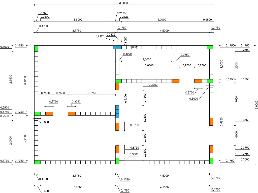
A wall thickness of 17.5 cm was chosen for all walls of the sample building to be built as part of the project. Only a few supplemental formats, which are all produced by the manufacturer, will be necessary in addition to the standard format (Fig. 3). Thus, it is not necessary to cut the masonry units to size on site.
Device for mortar application on calcium silicate units
The main task of IAB in the project is the conception and realisation of a mortar application device as a process unit prior to the unit-laying by the cable robot itself. The focus of the research activities is on optimisation and automation of the following process steps:
Gripping of units of different lengths from their place of storage
Application of thin-bed mortar on one side of the unit
Provision of mortared units for the cable roboter at defined handover points
The environmental conditions of an outdoors construction site were taken into account in the conception, e.g. by using dirt resistant components which are easy to mount. In addition, the specific requirements of the cable robot, the human machine interaction had to be considered in the development of the mortar application device.
As a part of development, tests with e.g. commercially available mortar rollers and mortar sledges were carried out to better assess the possibilities of automation and to create processes similar to those on construction sites. The tests showed process uncertainties concerning the planned automation because the mortar sledge will apply mortar on only one unit in contrast to the usual construction processes. Taken as a whole, it is noted that the process reliability depends on the mortar consistency and the mortar application speed. In addition, commercially available devices didn`t provide a sufficient leak-proofness at rest. The mortar flowed out of the openings of the mortar sledge already after a short time. These process uncertainties require the development of a new mortar application concept that will redefine the state of the art.
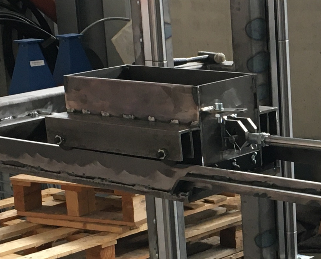
Based on the scientific competence and wide expertise of IAB in the field of block making machines, the idea arose to modify the principle of the charging hopper used in concrete block machines. The thin-bed mortar shall be applied on the unit by a recipocrating movement. Preliminary tests showed that a clean and reliable mortar application from above is possible by using this method. A detailed draft, which ensures even the leak-proofness at rest, was prepared for the developed solution (Fig. 4).
The new method of mortar application required a rotation of the masonry unit prior to the delivery to the cable robot so that the mortar is at the unit bottom to ensure a full mortar compound with the previously set layer of masonry units. This places special requirements for the adhesion between masonry unit and thin-bed mortar because it has to resist gravity as well as the very high starting and stopping accelerations of the cable robot. Prior tests with a special test stand for transport of mortared units showed possible shocks up to 13.5 G (G = 9.81 m/s2) until the fresh mortar peels off.
Standard calcium silicate units with a width of 175 mm, a height of 248 mm and various lengths were in the focus of planning the grab. The dimensions arose from the building concept (Fig. 3). Flat lintels and cut units for window and door openings have to be easy to handle for the cable robot. In addition, the handover point between grab and cable robot should grow with the building, otherwise collisions between the cables of the robot and the walls will occur. A maximum handover height of 3 m from the ground was agreed for the realisation of the functional model. But in future greater handover heights are intended to enable the use in construction of multi-storey buildings.
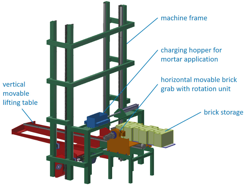
A preferred variant (Fig. 5) was chosen from all the concepts created in the context of handling the complex task. This variant was constructively developed further (Fig. 6). It is characterised by using components that are sturdy and suitable for use on construction sites, e. g. racks with gear drives as well as electrically or pneumatically working linear actuators.
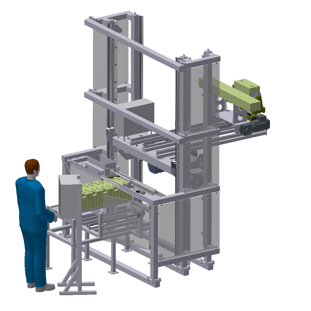
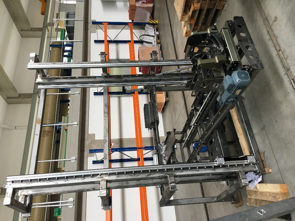
The components produced or purchased parts supplied by WESOMA GmbH Weimar are currently being assembled (Fig. 7) to enable a promptly pretesting of the mortar application device.
Cable robot for the automated masonry of calcium silicate units
A cable robot (Fig. 1) uses a cable set, which is fixed to a platform in a parallel topology, to carry its payload. The platform is the part of the cable robot that carries the payload. The cables are controlled by computer-controlled cable winches with electric servo motors to regulate the tension and lengths of the cables and steer the payload along defined ways. Eight cables are used in the project, which are controlled by a central control system via modern fieldbus communication. The legths of the cables are steadily determined using the winch angles. Simultaneously the cable tensions are permanently determined, controlled and monitored by the control system to ensure the safe and precise placement of the units. The platform is constructed in the form of a cuboid, which carries the payload (units) and contains further mechatronic components that are necessary for the automation of masonry construction.
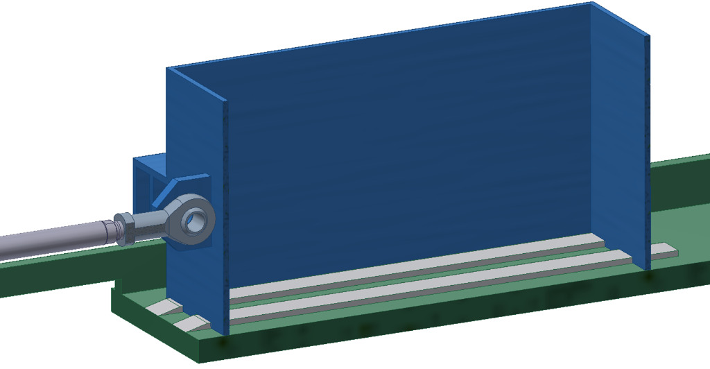
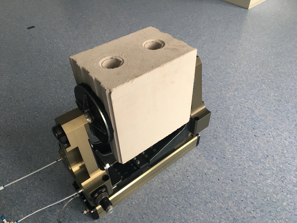
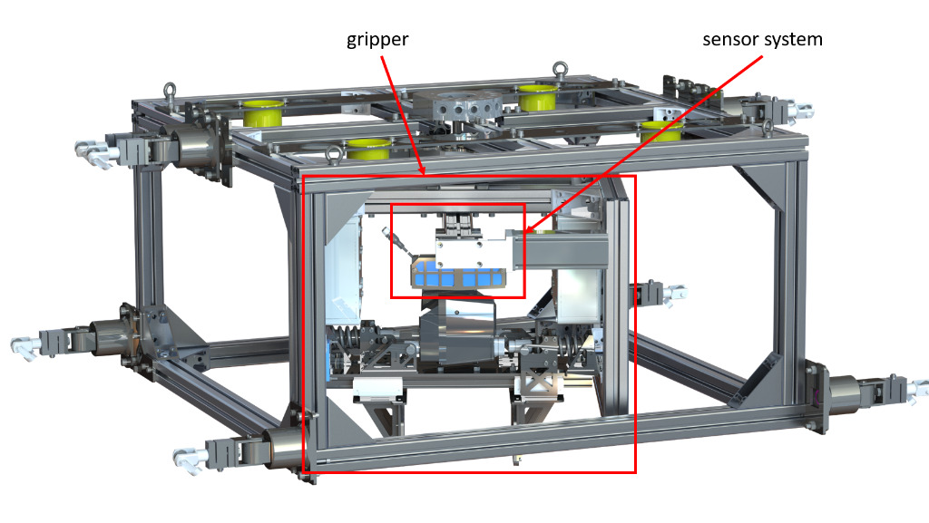
To grab the payload, a gripper system (Fig. 8) was developed taking into account process technical requirements and general safety. An integral component of the gripper system is the internal cage, which is able to revolve round a vertical axis and carries the gripper. Thus, it is possible to turn to revolve the payload round a vertical axis up to 360°. The gripper enables via pressure springs the passive hold of the payload and can be opened electromechanically for picking up and setting down. The maximum weight of the payload, so of the unit or the flat lintel, is 100 kg. To ensure a reliable process flow, the length of the unit shouldn’t be less then the contact surface of the gripper. It is necessary for the automated masonry construction to precisely measure the unit to be gripped and enable a repeatable grip. Therefore, the gripper system was expanded by a sensor concept in addition to the mechanical components. Two laser distance sensors directed vertically downwards were mounted in the internal cage and are moveable by an actuated linear unit. The moveable sensors provide the possibility to measure the unit before gripping and to position it precisely to already built masonry walls. The electronic system and the bus components for the communication with the master computer are placed in two little switch boxes laterally at the gripper system. The platform and the gripper system are connected to the main switching cabinet by a cable for communication and power supply.
The attachment points of the cables to the platform have to be clearly defined to ensure an adequate positioning accuracy of the robot platform. New precise attachment points were designed because the tolerable position deviation in the project is quite small in relation to the workspace. Now the cable is led with roller bearings over two axes.
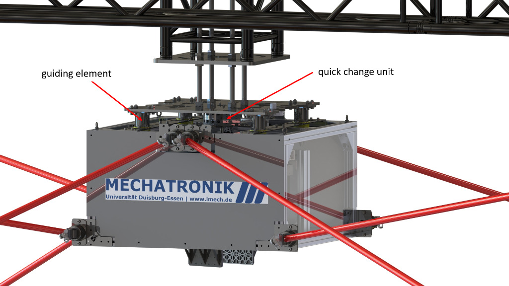
Prior to the use of the cable robot the platform should be referenced in the start position. In this step all cables will be tightened with a predefined force to stretch the plastic fibres of the cables and to reference the sensors to cable force and cable legth. A set down device is necessary which the platform will be fixed at in the start position to prevent a change of position during referencing. The start position is known so that the length of the cables at this point is known as well. In contrast to other applications, the set down device of automated masonry construction can’t be placed on the floor. As soon as the robot has constructed a building, it is not possible to let the platform down to the floor because of the risk of collisions between the cables and the building. Therefore, the set down device was fixed at the upper part of the robot frame (Fig. 9). A quick-change unit from industrial robotics (tool changing device) was first used in this project to lock the platform in the set down device pneumatically. The passively holding of the platform is here as important as for the unit grab to prevent that the platform falls from the set down device in case of deactivation or a failure. The acceptable misalignment during the retraction of the platform to the quick-change unit is relatively low, because these systems are normally used for robots with a workspace that is a small part of the cable robot’s workspace. Therefore, further guiding elements for a larger tolerance range are installed at the platform.
In order to move the platform over the construction site, the site has to be traversed by a frame, which carries the cable winches or pulleys that lead the cables from above into the workspace of the cable robot. The workspace is defined by the geometry of the pulleys as well as by the limits that are acceptable for the cable tension. The cable tension limits were defined for the project with minimum 100 N and maximum 5000 N. Thus, on the one hand the loads on the frame and the components are limited and on the other hand a sufficiently large workspace can be achieved. The geometry of the cable robot was defined using multi body simulation in that way, that the volume and form of the workspace as well as the stiffness against environmental influences such as wind are sufficient.
Compared to robot arms with serial structure such as the system Hadrian X, the cable robot as a modular and expandable lightweight construction system offers the following advantages:
climbing ability over several storeys (analogous to cranes)
high stiffness
large workspace
very high speed
The risk of collision might be caused by the cables, especially if they are led to the platform from below. This is sometimes necessary to reach the required workspace or stiffness. Therefore, the lower pulleys are designed mobile in the project. This enables to prevent collisions and to realise a large working area.
A digital twin for the design and simulative testing will be created parallel to the construction work. All planned parameters such as masses, geometrical quantities or motor data will be included in this step. The digital twin provides the possibility to simulate the process on the basis of BIM data and to check it for potential errors. In addition, this tool enables the generation of paths along which the units will be led. Every path will be checked for potential collisions, such as between robot and the already constructed building, and can be optimised with regard to process time, energy demand, maximum power or obstacle avoidance. For the optimisation, mathematical algorithms vary the path as well as pulley position over time in order to achieve the best possible results. In addition, the digital twin will be used in future to develop the planned state machine for the control of all process steps and to parameterise the control algorithms of the cable robot.
Conclusion and outlook
The automated masonry construction with cable robots is a holistic approach which has the potential to revolutionise masonry construction. The concept offers not only the reduction of construction times and personnel costs but also a higher quality and consistent digitalisation of the process chain from planning to production and supply of construction materials to the construction of the building. Furthermore, the increasing skills shortage in the construction sector will be countered by the new approach. The next planed step in the running project is the combination of the here presented results in a functional model. This will be the basis for the transfer of technology into construction practice.
Acknowledgement
The research project was sponsored within the framework of the program for Joint Industrial Research (IGF) (IGF project no.: 20061 BG) by the Federal Ministry for Economic Affairs and Energy (BMWi) via the Federation of Industrial Research Associations (AiF e. V.) on the basis of a resolution of the German Bundestag as well as the Ministry of Regional Identity, Communities and Local Government, Building and Gender Equality of the Land of North Rhine-Westphalia as part of the program ˮLong-term experimental investigation and demonstration of automated masonry construction and 3D printing with cable robotsˮ.

![]()
![]()
![]()